· Outer Diameter (OD): 5 mm – 200 mm
· Wall Thickness (WT): 0.5 mm – 20 mm
· Most Common Range:
→ OD: 10–120 mm
→ WT: 0.5–12 mm
Cold drawn pipes offer tighter tolerances and better surface finish than hot rolled pipes.
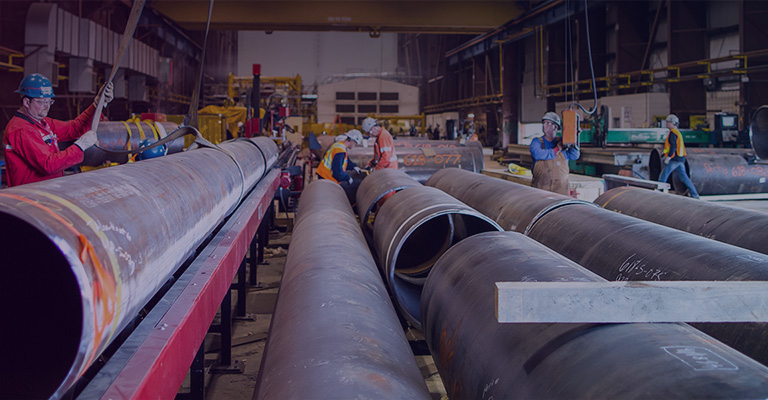
Cold drawn seamless steel pipes are primarily used in applications requiring high dimensional accuracy and superior surface finish.
They are typically categorized into three groups based on outer diameter, allowing for quick and efficient specification selection.
1.1 Small Precision Tubes (OD 5–50 mm)
These tubes are commonly used in hydraulic systems, automotive components, and precision machinery, where tight tolerances and uniform wall thickness are critical.
|
Outer Diameter (OD)
|
Wall Thickness (WT)
|
Typical Application Fields
|
|
5 – 10 mm
|
0.5 – 2.0 mm
|
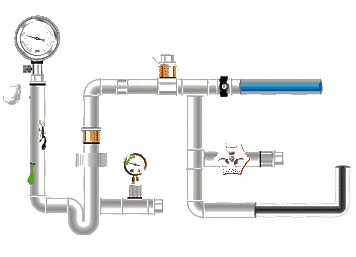
Instrument tubing, pressure sensors, gauge systems, precision measurement lines
|
|
10 – 25 mm
|
0.5 – 3.0 mm
|
Automotive components, shock absorber tubes, small hydraulic cylinders, drive systems
|
|
25 – 50 mm
|
1.0 – 5.0 mm
|
Hydraulic pipelines, piston rods, precision bushings, medium-pressure fluid systems
|
Thin-walled tubes (<2 mm) are almost exclusively produced by cold drawing, as hot rolling cannot achieve the required precision.
Typical tolerances:
· OD: ±0.05 mm
· WT: ±5%
(Compliant with GB/T 3639 / DIN 2391 precision grade)
1.2 Medium Precision Tubes (OD 50–120 mm)
This range represents the mainstream application segment for cold drawn seamless steel pipes, widely used in hydraulic cylinders and construction machinery components.
|
Outer Diameter (OD)
|
Wall Thickness (WT)
|
Typical Application Fields
|
|
50 – 80 mm
|
2.0 – 6.0 mm
|
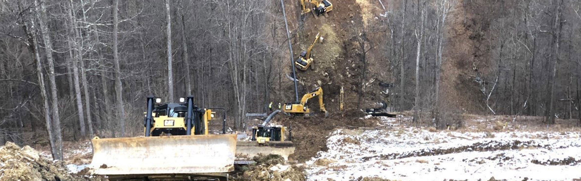
Standard hydraulic cylinder tubes, construction machinery hydraulic cylinders, industrial lifting systems
|
|
80 – 100 mm
|
3.0 – 8.0 mm
|
Excavator hydraulic cylinders, heavy-duty construction equipment components, earth-moving machinery systems
|
|
100 – 120 mm
|
4.0 – 12.0 mm
|
Large hydraulic cylinders, forging press cylinders, high-load industrial hydraulic systems
|
This range is the most commonly used in hydraulic systems.
Typical tolerances:
· OD: ±0.08 mm
· WT: ±5%–8%
1.3 Large Cold Drawn Tubes (OD 120–200 mm)
Large-diameter cold drawn pipes are less common and are highly dependent on the manufacturer’s capabilities and equipment limitations.
|
Outer Diameter (OD)
|
Wall Thickness (WT)
|
Typical Application Fields
|
|
120 – 150 mm
|
5.0 – 12.0 mm
|
Large hydraulic cylinders, tunnel boring machine (TBM) structural components, heavy construction equipment systems
|
|
150 – 200 mm
|
6.0 – 20.0 mm
|
Specialized industrial equipment, ultra-heavy-duty hydraulic cylinders, mining and infrastructure machinery systems
|
Important Notes:
· For pipes with an OD greater than 120 mm, production capability limits should be confirmed with the manufacturer in advance.
· If tolerance requirements are relatively loose (≥ IT10), a hot rolled + honing process is usually more cost-effective.
· Cold drawn pipes in this range typically have longer lead times and are 30%–50% more expensive.
Cold Drawn Seamless Steel Pipe Size Chart (Final Version)
|
Outer Diameter (OD, mm)
|
Wall Thickness (WT, mm)
|
|
Small Precision Tubes (4–20 mm)
|
|
4
|
0.5 / 0.8 / 1.0 / 1.2
|
|
5
|
0.5 / 0.8 / 1.0 / 1.2
|
|
6
|
0.5 / 0.8 / 1.0 / 1.2 / 1.5 / 1.8 / 2.0
|
|
7
|
0.5 / 0.8 / 1.0 / 1.2 / 1.5 / 1.8 / 2.0
|
|
8
|
0.5 / 0.8 / 1.0 / 1.2 / 1.5 / 1.8 / 2.0 / 2.2 / 2.5
|
|
9
|
0.5 – 2.8
|
|
10
|
0.5 – 3.0
|
|
12
|
0.5 – 4.0
|
|
14
|
0.5 – 4.5
|
|
15
|
0.5 – 5.0
|
|
16
|
0.5 – 6.0
|
|
18
|
0.5 – 6.0
|
|
20
|
0.5 – 7.0
|
|
Medium Precision Tubes (20–50 mm)
|
|
22
|
0.5 – 7.0
|
|
25
|
0.5 – 8.0
|
|
26
|
0.5 – 8.0
|
|
28
|
0.5 – 8.0
|
|
30
|
0.5 – 10
|
|
32
|
0.5 – 10
|
|
35
|
0.5 – 10
|
|
38
|
0.5 – 10
|
|
40
|
0.5 – 10
|
|
42
|
1.0 – 10
|
|
45
|
1.0 – 10
|
|
48
|
1.0 – 10
|
|
50
|
1.0 – 10
|
|
Hydraulic & Engineering Use (50–100 mm)
|
|
55
|
1.0 – 12
|
|
60
|
1.0 – 12
|
|
65
|
1.0 – 14
|
|
70
|
1.0 – 14
|
|
75
|
1.0 – 16
|
|
80
|
1.0 – 16
|
|
85
|
1.5 – 16
|
|
90
|
1.5 – 16
|
|
95
|
2.0 – 18
|
|
100
|
2.0 – 18
|
|
Large Diameter Tubes (100–200 mm)
|
|
110
|
2.0 – 18
|
|
120
|
2.0 – 18
|
|
130
|
2.5 – 18
|
|
140
|
2.5 – 18
|
|
150
|
3.0 – 20
|
|
160
|
3.0 – 20
|
|
170
|
3.0 – 20
|
|
180
|
3.5 – 20
|
|
190
|
3.5 – 20
|
|
200
|
3.5 – 20
|
2. How to Choose the Right Cold Drawn Seamless Steel Pipe
In real-world engineering, selecting a pipe size is not simply about picking a number from a standard chart. It involves balancing outer diameter, wall thickness, and tolerance.
The following four principles are more aligned with practical engineering decisions than relying solely on tables.
2.1 Start with Outer Diameter First
Many engineers tend to select wall thickness based on pressure first. However, for cold drawn pipes, outer diameter (OD) determines process feasibility and cost range.
(1) OD ≤ 50 mm: Precision small tubes
Focus on dimensional consistency and surface quality.
Typical applications: instrumentation, automotive sensors, small cylinders.
Thin-walled tubes (<2 mm) in this range are almost exclusively produced by cold drawing.
(2) OD 50–120 mm: General-purpose range
Most hydraulic cylinders and construction machinery fall within this range.
Specifications are widely available, lead times are stable, and suppliers are well-established.
Manufacturing processes in this range are mature, with minimal production constraints.
(3) OD > 120 mm: Equipment capability limit
Production feasibility must be confirmed with the manufacturer.
If tolerance requirements are not strict (≥ IT10), hot rolled + honing is often more cost-effective.
As a rule of thumb, first determine whether the OD falls within the 50–120 mm “optimal range”. This decision takes priority over wall thickness selection.
2.2 Match WT to Pressure
Cold drawn pipes are commonly used in hydraulic systems, and wall thickness selection typically follows practical experience ranges:
With a fixed OD:
WT 2–3 mm: Low-pressure or structural use
(e.g., pneumatic lines, support components)
WT 3–5 mm: Standard hydraulic systems
(e.g., typical hydraulic cylinders)
WT ≥ 6 mm: High-pressure or impact conditions
(e.g., construction machinery, heavy-duty equipment)
Increasing wall thickness also increases material cost and machining difficulty (such as boring and honing).
Final design should always be verified according to standards such as ASME B31.3 or GB/T 20801.
2.3 Tolerance Grade Often Matters More Than Size Itself
For example, an OD 80 × 5 mm pipe can perform very differently depending on its tolerance grade.
(1) Standard cold drawn (IT10–IT11):
Suitable for general structural or fluid transport applications.
Machining allowance is typically required.
(2) Precision cold drawn (IT8–IT9):
Ideal for mating components or hydraulic cylinders.
Offers minimal machining allowance, stable assembly, and lower rejection rates.
In applications such as hydraulic cylinder tubes, precision bushings, and automated assembly components, precision grade is usually specified directly.
Although the price difference is typically 10–20%, the savings in machining allowance and assembly cost are often significantly greater.
2.4 Typical Engineering Matching (Reference)
Once the outer diameter and service conditions are defined, the following common engineering combinations can be used as a reference:
|
Application Field
|
Recommended Standard
|
Recommended Manufacturing Process
|
Recommended Delivery Condition
|
|
Hydraulic cylinder tubes, construction machinery systems
|
DIN 2391 / GB/T 3639
|
Precision cold drawn
|
BK or BKS (stress-relieved / annealed)
|
|
Heat exchanger tubes, condensers
|
ASTM A179
|
Precision cold drawn
|
Cold drawn (hard condition)
|
|
High-temperature pressure piping (>400°C)
|
ASTM A106
|
Cold drawn + heat treatment
|
Normalized after cold drawing
|
|
Precision bushings, mating mechanical components
|
GB/T 3639
|
Precision cold drawn
|
BK (hard) or BKS (semi-hard)
|
|
General structural parts, low-pressure fluid systems
|
General specification (no strict standard requirement)
|
Standard cold drawn
|
As cold drawn condition
|
Selection workflow:
1.Confirm whether the OD falls within the feasible range for cold drawing
2.Determine wall thickness based on service conditions
3.Decide whether precision grade is required
4.Confirm downstream processing (e.g., honing, fit requirements)
3. Wall Thickness vs. Pressure Capacity
In practical applications of cold drawn seamless steel pipes, wall thickness directly determines pressure capacity and safety margin.
Due to variations in service conditions, materials, and design standards (ASME / GB), the following data should only be used as a preliminary engineering reference. Final design must be verified according to ASME B31.3 or GB/T 20801.
Taking Grade 20# steel with an OD of approximately 50 mm as an example, the empirical relationship between wall thickness and pressure capacity is as follows:
WT 2.0 mm: Approx. 12–16 MPa
Suitable for low-pressure pneumatic systems or non-pressure structural components
· WT 3.0 mm: Approx. 20–25 MPa
Common in medium-to-low pressure hydraulic systems
· WT 4.0 mm: Approx. 28–35 MPa
Suitable for standard hydraulic cylinder tubes
· WT 5.0 mm: Approx. 35–42 MPa
Used in high-pressure applications such as construction machinery
· WT ≥ 6.0 mm: Approx. ≥45 MPa
Typically used for heavy-duty or specialized high-pressure equipment
Note: Increasing wall thickness not only improves pressure resistance, but also increases material cost and machining difficulty (e.g., longer boring and honing time).
4. Common Standards and Delivery Conditions
Different standards define varying requirements for precision grades, heat treatment conditions, and inspection criteria. Selection should be aligned with the specific application scenario:
|
Standard
|
Typical Application Fields
|
Key Technical Characteristics
|
Delivery Condition
|
|
GB/T 3639
|
Precision machinery, hydraulic systems
|
Chinese benchmark for precision cold drawn tubes with strict dimensional tolerances
|
Cold drawn (BK) or cold drawn + stress-relieved annealed (BKS)
|
|
DIN 2391
|
Hydraulic cylinders, precision mechanical components
|
European precision tube standard equivalent to GB/T 3639, widely used in global engineering applications
|
Cold drawn (BK), annealed (GBK), normalized (NBK)
|
|
ASTM A106
|
High-temperature, high-pressure piping systems
|
Primarily hot-finished pipe standard; cold drawn condition must meet specified mechanical properties and be certified in MTR
|
Cold drawn condition permitted if compliant with A106 mechanical requirements
|
|
ASTM A179
|
Heat exchangers, condensers, thermal equipment
|
Cold drawing is mandatory for thin-wall seamless tubes; optimized for heat transfer performance
|
Cold drawn (mandatory condition)
|
|
EN 10216-1
|
European pressure piping systems
|
Seamless steel pipe standard allowing cold drawn conditions for pressure applications
|
Cold drawn (C condition), subject to compliance with EN requirements
|
Delivery Condition Descriptions
· BK (Cold Drawn):
Directly cold drawn without heat treatment; high hardness and significant residual stress.
· BKS (Cold Drawn + Stress-Relieved Annealed):
Partially relieves residual stress, offering improved dimensional stability.
· GBK (Annealed):
Fully recrystallized annealed condition; excellent ductility but reduced strength.
· NBK (Normalized):
Normalized heat treatment; uniform microstructure with balanced mechanical properties.
5. Conclusion
For projects with specific tolerance, pressure, or machining requirements, cold drawn pipe specifications may need to be adjusted accordingly.
If needed, technical details or size recommendations can be provided based on your application.
For further technical insights, you may also refer to:Treatment method for surface defects of cold drawn seamless steel pipe and Cold Drawn vs Hot Rolled Seamless Steel Pipe


 Eastern Steel Manufacturing Co.,Ltd not only improve product production and sales services, but also provide additional value-added services. As long as you need, we can complete your specific needs together.