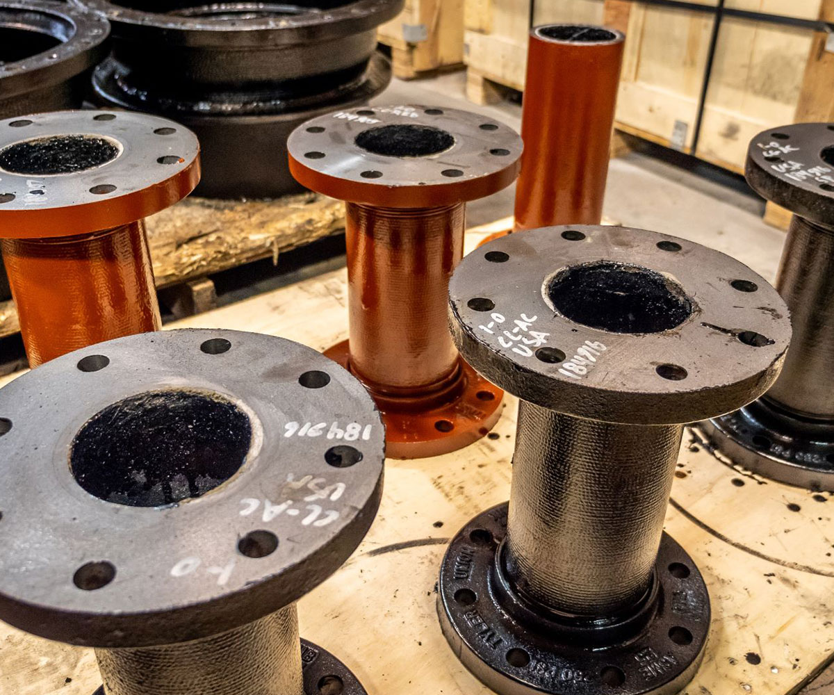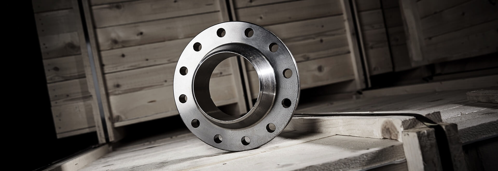
Flanges are interconnecting parts between pipes and tubes, used to connect between pipe ends,the main features of flange connection are easy disassembly and good sealing performance.
Carbon Steel Flange: ASTM A 105
Stainless Steel Flange: ASTM A 182
Size: 1/2”-60” (DN15-DN3000)
Pressure class: Class150-Class2500
Facing: RF/ FM/ M/ T G/ RF / FF / RTJ
Application: Water Supply, Oil, Gas, Petrochemical, Irrigation, Fire Services, General Industry, Construction.
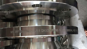
Marking: All Flanges when possible will display a heat number, size, table, grade and dimensional standard
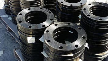
Plate steel flange: Plate flanges are mainly used for light duty, lower pressure or non-critical applications, commonly referring to AS2129, BS10 or AS4087 standards. The manufacturing method involves cutting and machining from plate steel
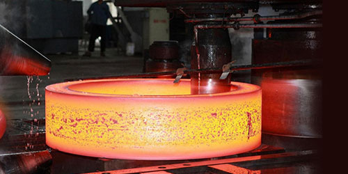
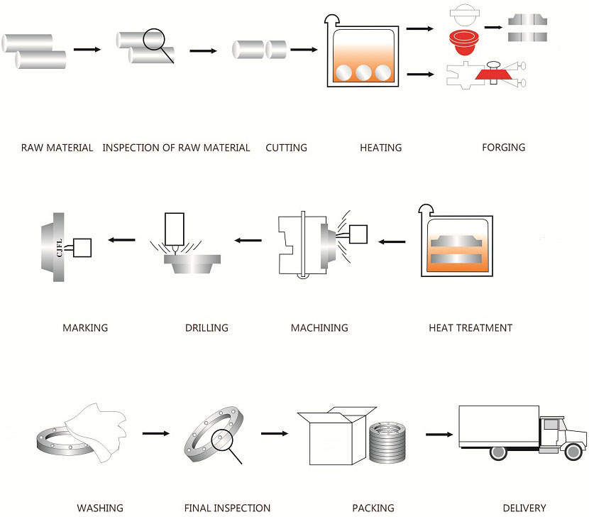
Forged steel flange: Forged Steel flanges are commonly used and specified in the Oil, Gas, Petrochemical and mining sectors, where pressure, temperature and safety considerations often specify the ANSI B16.5, ASME B16.47 or BS4504 standards. The manufacturing method involves the hot forging of suitable steels prior to final machining
BLIND FLANGES
Blind flanges are typically provided with a raised face, flat face, or RTJ facing. When a raised face is necessary for blind flanges, the standard height is 1/16" for blind flanges under 400#. For blind flanges of 400# and up, the standard blind flange raised face height is 1/4".
Material: Carbon, Alloy and Stainless Steel
Standards: ASTM A105, ASTM A182
Sizes: 1/2'' to 24'', Customized up to 48''
Thickness: Schedule 10(S) to SCH 160
Pressure Ratings: Class 150 to 2500
Face Type: RF, RTJ
|
SLIP-ON FLANGES
Slip on pipe flanges are typically provided with a raised or flat face. When a raised face is necessary for slip on pipe flanges, the standard height is 1/16" for slip on pipe flanges under 400#. For slip on pipe flanges of 400# and up, the standard slip on pipe flange raised face height is 1/4".
Standard: ASTM A105, ASTM A182
Material: Carbon Steel, Alloy Steel, Stainless Steel
Size: 1/2'' to 24'', customized up to 60''
Pressure Ratings: Class 150 to Class 2500
Face Type: RF, RTJ
|
WELD NECK FLANGES
Weld neck pipe flanges are typically provided with a raised face, flat face, or RTJ facing. When a raised face is necessary for weld neck pipe flanges, the standard height is 1/16" for weld neck pipe flanges under 400#. For weld neck pipe flanges of 400# and up, the standard weld neck pipe flange raised face height is 1/4".
Material: Carbon, Alloy and Stainless Steel
Standards: ASTM A105, ASTM A182
Sizes: 1/2'' to 24'', Customized up to 48''
Thickness: Schedule 10(S) to SCH 160
Pressure Ratings: Class 150 to 2500
Face Type: RF, RTJ
|
LAP JOINT FLANGES
Slip on Pipe flanges with a hub have published specifications that range from 1/2" thru 24". Sizes above 24" are produced as lap joints to slip on dimensions. Coastal Flange provides Lap Joint pipe flanges in all material grades, specifications and sizes.
Carbon steel: ASTM A105, A350 LF2
Stainless steel: A182 F304/F304L/F316/F316L/F321
Alloy steel: ASTM A182, GR F1, F11, F22, F5, F9, F91
Outer Diameters: 1/2'' to 24''
Wall Thickness Schedule: SCH 10, SCH 40, SCH 160
|
THREADED FLANGES
Threaded pipe flanges are typically provided with a raised face, flat face, or RTJ facing. When a raised face is necessary for threaded pipe flanges, the standard height is 1/16" for threaded pipe flanges under 400#. For threaded pipe flanges of 400# and up, the standard threaded pipe flange raised face height is 1/4".
Standard: ASTM A105, ASTM A182
Material: Carbon Steel, Stainless Steel, Alloy Steel
Size Range: 1/2'', 1'', 2'', 3'', 4'' to 24''
Pressure Class: Class 150 to 2500
Face: Raised face (RF), Ring type joint (RTJ)
|
SOCKET WELD FLANGES
Socket Weld pipe flanges are typically provided with a raised face, flat face, or RTJ facing. When a raised face is necessary for socket weld pipe flanges, the standard height is 1/16" for socket weld pipe flanges under 400#. For socket weld pipe flanges of 400# and up, the standard socket weld pipe flange raised face height is 1/4".
Standard:
Carbon steel ASTM A105, ASTM A350 LF1/2, ASTM A181
Alloy steel ASTM A182 F5, F9, F11, F22, F91
Stainless steel ASTM A182 F304/L, F316/L
Outer Diameters: 1/2 inch to 24 inch, up to 2500#
Special made: 24'' to 60'', up to 900#
Wall Thickness: Schedule 40 to 160
Pressure Ratings: Class 150 to Class 2500
Face Type: RF, RTJ
|
CLASS 150According to ASTM A/SA-105; ANSI B16.5
|
|
Nominal
Pipe
Size
|
Outside
Diam. of
Flange (O)
|
Thick.
of
Flange (C)
|
Diam.
of
Raised Face (R)
|
Diam.
of Hub
at Base (X)
|
Length
thru Hub
(Y)
|
Min.
Thread
Length
(T)
|
Min.
Counter
Bore (Q)
|
No. of
Holes
|
Diam. of
Holes
|
Diam. of
Bolts
|
Diam.
of Bolt
Circle
|
Approx.
Weight
(in Pounds)
|
|
½
|
3.5
|
0.44
|
1.38
|
1.19
|
0.62
|
0.62
|
|
4
|
0.62
|
0.5
|
2.38
|
1
|
|
¾
|
3.88
|
0.5
|
1.69
|
1.5
|
0.62
|
0.62
|
|
4
|
0.62
|
0.5
|
2.75
|
2
|
|
1
|
4.25
|
0.56
|
2
|
1.94
|
0.69
|
0.69
|
|
4
|
0.62
|
0.5
|
3.12
|
2
|
|
1 ¼
|
4.62
|
0.62
|
2.5
|
2.31
|
0.81
|
0.81
|
|
4
|
0.62
|
0.5
|
3.5
|
3
|
|
1 ½
|
5
|
0.69
|
2.88
|
2.56
|
0.88
|
0.88
|
|
4
|
0.62
|
0.5
|
3.88
|
3
|
|
2
|
6
|
0.75
|
3.62
|
3.06
|
1
|
1
|
|
4
|
0.75
|
0.62
|
4.75
|
5
|
|
2 ½
|
7
|
0.88
|
4.12
|
3.56
|
1.12
|
1.12
|
|
4
|
0.75
|
0.62
|
5.5
|
7
|
|
3
|
7.5
|
0.94
|
5
|
4.25
|
1.19
|
1.19
|
|
4
|
0.75
|
0.62
|
6
|
8
|
|
3 ½
|
8.5
|
0.94
|
5.5
|
4.81
|
1.25
|
1.25
|
|
8
|
0.75
|
0.62
|
7
|
11
|
|
4
|
9
|
0.94
|
6.19
|
5.31
|
1.31
|
1.31
|
|
8
|
0.75
|
0.62
|
7.5
|
13
|
|
5
|
10
|
0.94
|
7.31
|
6.44
|
1.44
|
1.44
|
|
8
|
0.88
|
0.75
|
8.5
|
15
|
|
6
|
11
|
1
|
8.5
|
7.56
|
1.56
|
1.56
|
|
8
|
0.88
|
0.75
|
9.5
|
19
|
|
8
|
13.5
|
1.12
|
10.62
|
9.69
|
1.75
|
1.75
|
|
8
|
0.88
|
0.75
|
11.75
|
30
|
|
10
|
16
|
1.19
|
12.75
|
12
|
1.94
|
1.94
|
|
12
|
1
|
0.88
|
14.25
|
43
|
|
12
|
19
|
1.25
|
15
|
14.38
|
2.19
|
2.19
|
|
12
|
1
|
0.88
|
17
|
64
|
|
14
|
21
|
1.38
|
16.25
|
15.75
|
2.25
|
2.25
|
|
12
|
1.12
|
1
|
18.75
|
90
|
|
16
|
23.5
|
1.44
|
18.5
|
18
|
2.5
|
2.5
|
|
16
|
1.12
|
1
|
21.25
|
98
|
|
18
|
25
|
1.56
|
21
|
19.88
|
2.69
|
2.69
|
|
16
|
1.25
|
1.13
|
22.75
|
130
|
|
20
|
27.5
|
1.69
|
23
|
22
|
2.88
|
2.88
|
|
20
|
1.25
|
1.12
|
25
|
165
|
|
24
|
32
|
1.88
|
27.25
|
26.12
|
3.25
|
3.25
|
|
20
|
1.38
|
1.25
|
29.5
|
220
|
|
CLASS 300According to ASTM A/SA-105; ANSI B16.5
|
|
Nominal
Pipe
Size
|
Outside
Diam. of
Flange (O)
|
Thick.
of
Flange (C)
|
Diam.
of
Raised Face
(R)
|
Diam.
of Hub
at Base
(X)
|
Length
thru Hub
(Y)
|
Min.
Thread
Length
(T)
|
Min.
Counter Bore
(Q)
|
No. of
Holes
|
Diam. of
Holes
|
Diam.
of Bolts
|
Diam.
of Bolt
Circle
|
Approx.
Weight
(in Pounds)
|
|
1/2
|
3.75
|
0.56
|
1.38
|
1.5
|
0.88
|
0.62
|
0.93
|
4
|
0.62
|
0.5
|
2.62
|
2
|
|
3/4
|
4.62
|
0.62
|
1.69
|
1.88
|
1
|
0.62
|
1.14
|
4
|
0.75
|
0.62
|
3.25
|
3
|
|
1
|
4.88
|
0.69
|
2
|
2.12
|
1.06
|
0.69
|
1.41
|
4
|
0.75
|
0.62
|
3.5
|
3
|
|
1 1/4
|
5.25
|
0.75
|
2.5
|
2.5
|
1.06
|
0.81
|
1.75
|
4
|
0.75
|
0.62
|
3.88
|
4
|
|
1 1/2
|
6.12
|
0.81
|
2.88
|
2.75
|
1.19
|
0.88
|
1.99
|
4
|
0.88
|
0.75
|
4.5
|
6
|
|
2
|
6.5
|
0.88
|
3.62
|
3.31
|
1.31
|
1.12
|
2.5
|
8
|
0.75
|
0.62
|
5
|
7
|
|
2 1/2
|
7.5
|
1
|
4.12
|
3.94
|
1.5
|
1.25
|
3
|
8
|
0.88
|
0.75
|
5.88
|
10
|
|
3
|
8.25
|
1.12
|
5
|
4.62
|
1.69
|
1.25
|
3.63
|
8
|
0.88
|
0.75
|
6.62
|
13
|
|
3 1/2
|
9
|
1.19
|
5.5
|
5.25
|
1.75
|
1.44
|
4.13
|
8
|
0.88
|
0.75
|
7.25
|
17
|
|
4
|
10
|
1.25
|
6.19
|
5.75
|
1.88
|
1.44
|
4.63
|
8
|
0.88
|
0.75
|
7.88
|
22
|
|
5
|
11
|
1.38
|
7.31
|
7
|
2
|
1.69
|
5.69
|
8
|
0.88
|
0.75
|
9.25
|
28
|
|
6
|
12.5
|
1.44
|
8.5
|
8.12
|
2.06
|
1.81
|
6.75
|
12
|
0.88
|
0.75
|
10.62
|
39
|
|
8
|
15
|
1.62
|
10.62
|
10.25
|
2.44
|
2
|
8.75
|
12
|
1
|
0.88
|
13
|
58
|
|
10
|
17.5
|
1.88
|
12.75
|
12.62
|
2.62
|
2.19
|
10.88
|
16
|
1.12
|
1
|
15.25
|
81
|
|
12
|
20.5
|
2
|
15
|
14.75
|
2.88
|
2.38
|
12.94
|
16
|
1.25
|
1.12
|
17.75
|
115
|
|
14
|
23
|
2.12
|
16.25
|
16.75
|
3
|
2.5
|
14.19
|
20
|
1.25
|
1.12
|
20.25
|
165
|
|
16
|
25.5
|
2.25
|
18.5
|
19
|
3.25
|
2.69
|
16.19
|
20
|
1.38
|
1.25
|
22.5
|
190
|
|
18
|
28
|
2.38
|
21
|
21
|
3.5
|
2.75
|
18.19
|
24
|
1.38
|
1.25
|
24.75
|
250
|
|
20
|
30.5
|
2.5
|
23
|
23.12
|
3.75
|
2.88
|
20.19
|
24
|
1.38
|
1.25
|
27
|
315
|
|
24
|
36
|
2.75
|
27.25
|
27.62
|
4.19
|
3.25
|
24.19
|
24
|
1.62
|
1.5
|
32
|
475
|
|
CLASS 600According to ASTM A/SA-105; ANSI B16.5
|
|
Nominal
Pipe
Size
|
Outside
Diam. of
Flange (O)
|
Thick.
of
Flange
(C)
|
Diam.
of
Raised Face
(R)
|
Diam.
of Hub
at Base (X)
|
Length
thru Hub
(Y)
|
Min.
Thread
Length
(T)
|
Min.
Counter
Bore
(Q)
|
No. of
Holes
|
Diam. of
Holes
|
Diam. of
Bolts
|
Diam. of
Bolt Circle
|
Approx.
Weight
(in Pounds)
|
|
1/2
|
3.75
|
0.56
|
1.38
|
1.5
|
0.88
|
0.62
|
0.93
|
4
|
0.62
|
0.5
|
2.62
|
2
|
|
3/4
|
4.62
|
0.62
|
1.69
|
1.88
|
1
|
0.62
|
1.14
|
4
|
0.75
|
0.62
|
3.25
|
3
|
|
1
|
4.88
|
0.69
|
2
|
2.12
|
1.06
|
0.69
|
1.41
|
4
|
0.75
|
0.62
|
3.5
|
4
|
|
1 1/4
|
5.25
|
0.81
|
2.5
|
2.5
|
1.12
|
0.81
|
1.75
|
4
|
0.75
|
0.62
|
3.88
|
5
|
|
1 1/2
|
6.12
|
0.88
|
2.88
|
2.75
|
1.25
|
0.88
|
1.99
|
4
|
0.88
|
0.75
|
4.5
|
7
|
|
2
|
6.5
|
1
|
3.62
|
3.31
|
1.44
|
1.12
|
2.5
|
8
|
0.75
|
0.62
|
5
|
9
|
|
2 1/2
|
7.5
|
1.12
|
4.12
|
3.94
|
1.62
|
1.25
|
3
|
8
|
0.88
|
0.75
|
5.88
|
13
|
|
3
|
8.25
|
1.25
|
5
|
4.62
|
1.81
|
1.38
|
3.63
|
8
|
0.88
|
0.75
|
6.62
|
16
|
|
3 1/2
|
9
|
1.38
|
5.5
|
5.25
|
1.94
|
1.56
|
4.13
|
8
|
1
|
0.88
|
7.25
|
21
|
|
4
|
10.75
|
1.5
|
6.19
|
6
|
2.12
|
1.62
|
4.63
|
8
|
1
|
0.88
|
8.5
|
37
|
|
5
|
13
|
1.75
|
7.31
|
7.44
|
2.38
|
1.88
|
5.69
|
8
|
1.12
|
1
|
10.5
|
63
|
|
6
|
14
|
1.88
|
8.5
|
8.75
|
2.62
|
2
|
6.75
|
12
|
1.12
|
1
|
11.5
|
80
|
|
8
|
16.5
|
2.19
|
10.62
|
10.75
|
3
|
2.25
|
8.75
|
12
|
1.25
|
1.12
|
13.75
|
115
|
|
10
|
20
|
2.5
|
12.75
|
13.5
|
3.38
|
2.56
|
10.88
|
16
|
1.38
|
1.25
|
17
|
170
|
|
12
|
22
|
2.62
|
15
|
15.75
|
3.62
|
2.75
|
12.94
|
20
|
1.38
|
1.25
|
19.25
|
200
|
|
14
|
23.75
|
2.75
|
16.25
|
17
|
3.69
|
2.88
|
14.19
|
20
|
1.5
|
1.38
|
20.75
|
230
|
|
16
|
27
|
3
|
18.5
|
19.5
|
4.19
|
3.06
|
16.19
|
20
|
1.62
|
1.5
|
23.75
|
330
|
|
18
|
29.25
|
3.25
|
21
|
21.5
|
4.62
|
3.12
|
18.19
|
20
|
1.75
|
1.63
|
25.75
|
400
|
|
20
|
32
|
3.5
|
23
|
24
|
5
|
3.25
|
20.19
|
24
|
1.75
|
1.62
|
28.5
|
510
|
|
24
|
37
|
4
|
27.25
|
28.25
|
5.5
|
3.62
|
24.19
|
24
|
2
|
1.88
|
33
|
730
|
|
CLASS 900According to ASTM A/SA-105; ANSI B16.5
|
|
Nominal
Pipe
Size
|
Outside
Diam. of
Flange (O)
|
Thick.
of
Flange
(C)
|
Diam.
of
Raised Face
(R)
|
Diam.
of Hub
at Base
(X)
|
Length
thru Hub (Y)
|
Min.
Thread
Length
(T)
|
Min.
Counter
Bore
(Q)
|
No. of
Holes
|
Diam. of
Holes
|
Diam. of
Bolts
|
Diam. of
Bolt Circle
|
Approx.
Weight
(in Pounds)
|
|
1/2
|
4.75
|
0.88
|
1.38
|
1.5
|
1.25
|
0.88
|
0.93
|
4
|
0.88
|
0.75
|
3.25
|
4
|
|
3/4
|
5.12
|
1
|
1.69
|
1.75
|
1.38
|
1
|
1.14
|
4
|
0.88
|
0.75
|
3.5
|
5
|
|
1
|
5.88
|
1.12
|
2
|
2.06
|
1.62
|
1.12
|
1.41
|
4
|
1
|
0.88
|
4
|
8
|
|
1 1/4
|
6.25
|
1.12
|
2.5
|
2.5
|
1.62
|
1.19
|
1.75
|
4
|
1
|
0.88
|
4.38
|
9
|
|
1 1/2
|
7
|
1.25
|
2.88
|
2.75
|
1.75
|
1.25
|
1.99
|
4
|
1.12
|
1
|
4.88
|
12
|
|
2
|
8.5
|
1.5
|
3.62
|
4.12
|
2.25
|
1.5
|
2.5
|
8
|
1
|
0.88
|
6.5
|
25
|
|
2 1/2
|
9.62
|
1.62
|
4.12
|
4.88
|
2.5
|
1.88
|
3
|
8
|
1.12
|
1
|
7.5
|
36
|
|
3
|
9.5
|
1.5
|
5
|
5
|
2.12
|
1.62
|
3.63
|
8
|
1
|
0.88
|
7.5
|
26
|
|
4
|
11.5
|
1.75
|
6.19
|
6.25
|
2.75
|
1.88
|
4.63
|
8
|
1.25
|
1.12
|
9.25
|
53
|
|
5
|
13.75
|
2
|
7.31
|
7.5
|
3.12
|
2.12
|
5.69
|
8
|
1.38
|
1.25
|
11
|
83
|
|
6
|
15
|
2.19
|
8.5
|
9.25
|
3.38
|
2.25
|
6.75
|
12
|
1.25
|
1.12
|
12.5
|
110
|
|
8
|
18.5
|
2.5
|
10.62
|
11.75
|
4.00
|
2.50
|
8.75
|
12
|
1.5
|
1.38
|
15.5
|
170
|
|
10
|
21.5
|
2.75
|
12.75
|
14.5
|
4.25
|
2.81
|
10.88
|
16
|
1.5
|
1.38
|
18.5
|
245
|
|
12
|
24
|
3.12
|
15
|
16.5
|
4.62
|
3
|
12.94
|
20
|
1.5
|
1.38
|
21
|
325
|
|
14
|
25.25
|
3.38
|
16.25
|
17.75
|
5.12
|
3.25
|
14.19
|
20
|
1.62
|
1.5
|
22
|
400
|
|
16
|
27.75
|
3.5
|
18.5
|
20
|
5.25
|
3.38
|
16.19
|
20
|
1.75
|
1.63
|
24.25
|
425
|
|
18
|
31
|
4
|
21
|
22.25
|
6
|
3.5
|
18.19
|
20
|
2
|
1.88
|
27
|
600
|
|
20
|
33.75
|
4.25
|
23
|
24.5
|
6.25
|
3.62
|
20.19
|
20
|
2.12
|
2
|
29.5
|
730
|
|
24
|
41
|
5.5
|
27.25
|
29.5
|
8
|
4
|
24.19
|
20
|
2.62
|
2.5
|
35.5
|
1400
|
|
CLASS 1500According to ASTM A/SA-105; ANSI B16.5
|
|
Nominal
Pipe
Size
|
Outside
Diam. of
Flange (O)
|
Thick.
of
Flange
(C)
|
Diam.
of
Raised Face
(R)
|
Diam.
of Hub
at Base
(X)
|
Length
thru Hub
(Y)
|
Min.
Thread
Length
(T)
|
Min.
Counter
Bore
(Q)
|
No. of
Holes
|
Diam. of
Holes
|
Diam. of
Bolts
|
Diam. of
Bolt Circle
|
Approx.
Weight
(in Pounds)
|
|
1/2
|
4.75
|
0.88
|
1.38
|
1.5
|
1.25
|
0.88
|
0.93
|
4
|
0.88
|
0.75
|
3.25
|
4
|
|
3/4
|
5.12
|
1
|
1.69
|
1.75
|
1.38
|
1
|
1.14
|
4
|
0.88
|
0.75
|
3.5
|
5
|
|
1
|
5.88
|
1.12
|
2
|
2.06
|
1.62
|
1.12
|
1.41
|
4
|
1
|
0.88
|
4
|
8
|
|
1 1/4
|
6.25
|
1.12
|
2.5
|
2.5
|
1.62
|
1.19
|
1.75
|
4
|
1
|
0.88
|
4.38
|
9
|
|
1 1/2
|
7
|
1.25
|
2.88
|
2.75
|
1.75
|
1.25
|
1.99
|
4
|
1.12
|
1
|
4.88
|
12
|
|
2
|
8.5
|
1.5
|
3.62
|
4.12
|
2.25
|
1.5
|
2.5
|
8
|
1
|
0.88
|
6.5
|
25
|
|
2 1/2
|
9.62
|
1.62
|
4.12
|
4.88
|
2.5
|
1.88
|
3
|
8
|
1.12
|
1
|
7.5
|
36
|




 Eastern Steel Manufacturing Co.,Ltd not only improve product production and sales services, but also provide additional value-added services. As long as you need, we can complete your specific needs together.
