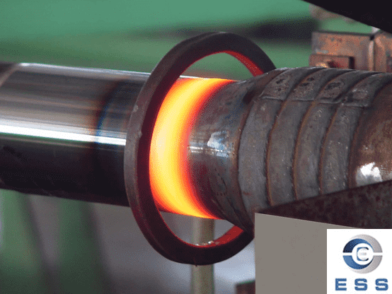
High-frequency welding originated in the 1950s. It is a new welding process that uses the skin effect and adjacent effect generated by high-frequency current to connect steel plates and other metal materials. The emergence and maturity of high-frequency welding technology has directly promoted the huge development of the straight seam welded pipe industry, which is a key process in the production of
erw pipe. The quality of high-frequency welding directly affects the overall strength, quality level and production speed of welded pipe products.
1. The basic principle of high frequency welding
The so-called high frequency is relative to the AC current frequency of 50Hz, generally refers to the high frequency current of 50KHz~400KHz. When a high-frequency current passes through a metal conductor, two peculiar effects will occur: the skin effect and the proximity effect. High-frequency welding uses these two effects to
weld steel pipes. So, what are these two effects? The skin effect means that when an alternating current of a certain frequency passes through the same conductor, the current density is not uniformly distributed on all sections of the conductor, and it will mainly concentrate on the surface of the conductor, that is, the density of the current on the conductor surface is high, The density inside the conductor is small, so we call it "skin effect" vividly. The skin effect is usually measured by the penetration depth of the current. The smaller the penetration depth value, the more significant the skin effect is. This penetration depth is proportional to the square root of the resistivity of the conductor and inversely proportional to the square root of the frequency and permeability. In layman's terms, the higher the frequency, the more concentrated the current is on the surface of the steel plate; the lower the frequency, the more dispersed the surface current. It must be noted that although steel is a conductor, its permeability will decrease as the temperature increases, that is to say, when the temperature of the steel plate increases, the permeability will decrease and the skin effect will decrease.
The proximity effect means that when high-frequency current flows in opposite directions in two adjacent conductors, the current will concentrate on the edges of the two conductors that are close to each other. Even if the two conductors have another shorter side, the current will not flow along the Shorter routes flow, we call this effect: the "proximity effect". The proximity effect is essentially due to the role of inductive reactance, which plays a dominant role in high-frequency currents. The proximity effect increases as the frequency increases and the spacing between adjacent conductors increases. If a magnetic core is added around the adjacent conductors, the high-frequency current will be more concentrated on the surface of the workpiece. These two effects are the basis for realizing metal high-frequency welding. High-frequency welding uses the skin effect to concentrate the energy of high-frequency current on the surface of the workpiece; and uses the proximity effect to control the location and range of the high-frequency current flow path. The speed of the current is very fast, it can heat and melt the edges of the adjacent steel plates in a very short time, and realize the butt joint by extrusion.
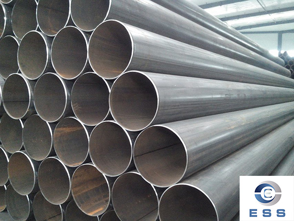
2. Structure and working principle of high frequency welding equipment
After understanding the principle of high frequency welding, it is necessary to have the necessary technical means to realize it. High-frequency welding equipment is an electrical-mechanical system used to realize high-frequency welding. High-frequency welding equipment is composed of a high-frequency welding machine and a
welded pipe forming machine. Among them, the high-frequency welding machine is generally composed of a high-frequency generator and a feeding device. Its function is to generate high-frequency current and control it; the forming machine is composed of a squeeze roller frame, and its function is to The molten part is extruded to remove the oxide layer and impurities on the surface of the steel plate, so that the steel plate is completely fused into one. High-frequency generator The high-frequency generator used on the welded pipe unit in the past is a three-loop: high-frequency generator set; solid-state frequency converter; electronic high-frequency oscillator, and later basically improved to a single-circuit. There are many ways to adjust the output power of high frequency oscillator, such as autotransformer, reactance method, thyristor method, etc. The feeding device is used to transmit high-frequency current to the tube, including electrode contacts, induction coils and impedance devices. In contact welding, wear-resistant copper-tungsten alloy electrode contacts are generally used, and copper induction coils are used in induction welding.
The main component of the resistor is the magnetic core, and its function is to increase the inductive reactance of the surface of the tube to reduce the inactive current and improve the welding speed. The magnetic core of the resistor is made of ferrite, and its Curie point temperature is required to be not lower than 310°. The Curie point temperature is an important indicator of the magnetic core. The closer you get, the higher the welding efficiency. In recent years, some large companies in the world have begun to adopt the solid-state modular structure, which greatly improves the welding reliability and ensures the welding quality. For example, the WELDACG2800 high-frequency welding machine designed by EFD Company consists of the following parts: rectification and control unit (CRU), inverter, matching and compensation unit (IMC), DC cable between CRU and IMC, IMC to coil or contact components. The two main parts of the machine are the CRU and the IMC. The CRU consists of a rectifier section with a main isolation switch and a full-bridge diode rectifier (which converts alternating current to direct current), a controller with controls and interfaces to external control equipment. The IMC consists of the inverter module, a matching transformer and a capacitor bank to provide the necessary reactive power for the induction coil.
The main supply voltage (3-phase 480V) is sent to the main rectifier through the main isolation switch. In the main rectifier, the main voltage is converted to 640V DC and connected to the main DC cable via the bus bar. Direct current is sent to the IMC through a direct current transmission line consisting of several parallel cables. The DC cable is terminated on the IMC unit bus. The inverter module of the inverter part is connected in parallel with the DC bus through the high-speed DC fuse. The DC capacitors are also connected together with the DC bus.
Each inverter module constitutes a full-bridge IGBT triode inverter. The drive circuit of the triode is on a printed circuit board in the inverter module. The direct current is converted into high frequency alternating current by the inverter. According to the specific load, the frequency range of AC power is in the range of 100-150KH. To adjust the inverters according to the load, all inverters are connected in parallel with matching transformers. The transformer has several main windings connected in parallel, and a secondary winding. The turns ratio of the transformer is fixed.
The output capacitor consists of several parallel capacitor modules. The capacitor is connected in series with the induction coil, so the output circuit is also series compensated. The function of the capacitor is to compensate according to the reactive power requirement of the induction coil, and to make the resonant frequency of the output circuit reach the required value through this compensation. The frequency control system is designed to keep the triode always working at the resonant frequency of the system. The resonance frequency is determined by measuring the frequency of the output current. This frequency is then used as the time base signal to turn on the transistor. The triode driver card sends a signal to each triode on each inverter module to control when the triode is turned on and when it is turned off.
The output power control of the induction heating system is controlled by controlling the output current of the inverter. The above control is accomplished by a power control card used to control the triode driver. The output power reference value is given by the power reference potentiometer on the IMC control panel, or output to the control system by the external control panel. After this value is transmitted to the system controller, it is compared with the DC power value measured by the rectifier unit measurement system. The controller includes a limit function that calculates a new output current setpoint based on the comparison of the reference power value with the DC power measurement. The output power set value calculated by the controller is sent to the power control card, which will limit the output current according to the new set value. The alarm system is based on the input signal of the alarm card in the IMC and the signals sent by various monitoring equipment in the IMC and CRU.
come to work. Alarms will be displayed on the workbench.
Control and Rectifier Unit (CRU) Inverter, Matching and Compensation Unit (IMC) DC Cable Output Power Bus, Coils and Contact Head Connections Cooling System is mounted in a self-supporting steel frame, all components are linked into a complete unit. system package
Including: circulating pump with motor, heat exchanger (water/water), compensation container, pressure gauge on output process side (secondary output), main water inlet temperature control valve, control valve and electrical cabinet. The heat exchanger at the main inlet side uses untreated tributary water as cooling water, and the heat exchanger at the secondary side uses purified neutral drinking water as cooling water. Raw water is controlled by a thermostatic valve, which measures the temperature at the secondary output. The steel frame can be bolted to the door.
3. The main points of high frequency welding quality control
There are many factors that affect the quality of high-frequency welding, and these factors interact in the same system. If one factor changes, other factors will also change with it. Therefore, in the high frequency adjustment, it is not enough to only pay attention to local adjustments such as frequency, current or extrusion amount. This adjustment must be based on the specific conditions of the entire molding system, from all aspects related to high frequency welding. Adjustment.
Read more : seamless vs welded pipe or ERW Pipe Specifications and Models




 Eastern Steel Manufacturing Co.,Ltd not only improve product production and sales services, but also provide additional value-added services. As long as you need, we can complete your specific needs together.
