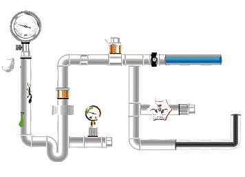
Hydraulic
tube flow rate refers to the volume of liquid passing through the pipe
cross-section per unit time, typically measured in liters per minute (L/min) or
cubic meters per second (m³/s). It is a core parameter
in hydraulic system design, directly affecting the speed and efficiency of
actuators.
Key Factors Influencing Hydraulic Tube
Flow Rate
1. Relationship Between Pipe Diameter and
Flow Rate
According to the Bernoulli equation, flow
rate Q = π × (d/2)² × v (d is
the inner diameter, v is the flow rate). For example, a DN15 (16mm inner
diameter) steel pipe with a flow rate of 4 m/s has a theoretical flow rate of ≈30 L/min.
2. Fluid Properties
ISO VG46 hydraulic oil has a viscosity of
approximately 46 cSt at 40°C. Excessive viscosity can
result in a 5%-15% reduction in flow rate (data source: US NFPA standards).
3. Pressure Loss
The formula for flow resistance along the
line is ΔP = λ × (L/d) × (ρv²/2), where λ is the friction coefficient. Actual measurements show that a
10-meter-long DN20 hose has a pressure loss of approximately 0.3 MPa at a flow
rate of 30 L/min.
Flow Formula for Hydraulic Piping
The formula for calculating flow in
hydraulic piping is: Q = V × A, where Q represents the
flow rate, V represents the flow velocity, and A represents the pipe
cross-sectional area.
This formula indicates that flow rate is
directly proportional to the flow velocity and the pipe cross-sectional area.
Therefore, when designing and selecting hydraulic piping, it is necessary to
appropriately determine the flow velocity and pipe cross-sectional area to
achieve the required flow rate.
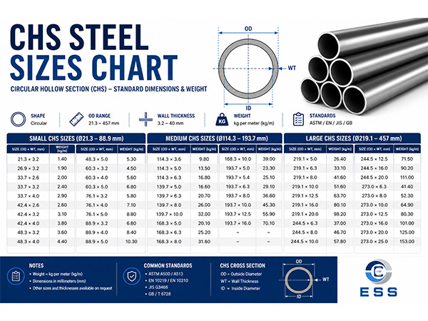
Comparison of Flow Parameters of Typical
Hydraulic Tubes
The following table lists reference flow
rates under common operating conditions:
|
Pipe Type
|
Inner Diameter (mm)
|
Recommended Flow Velocity (m/s)
|
Maximum Flow Rate (L/min)
|
|
Hard Steel Pipe
|
10
|
4.0
|
18.8
|
|
Soft Tube
|
25
|
6.0
|
176.6
|
|
Copper Pipe
|
12
|
3.5
|
23.7
|
Note: Data is based on ISO 18752, with a
safety factor of 1.5.
Hydraulic Tube Flow Chart
|
Nominal Diameter
|
Pipe Outer Diameter (mm)
|
Connection Thread (mm)
|
Nominal Pressure pn/MPa
|
Recommended Flow (L/min)
|
|
≤2.5
|
≤8
|
≤16
|
≤25
|
≤31.5
|
|
mm
|
in
|
Pipe Wall Thickness/mm
|
|
3
|
|
6
|
|
|
GB/T7306
|
1
|
1
|
1
|
1
|
1.4
|
0.63
|
|
4
|
|
8
|
|
|
Outer diameter and number of threads
|
1
|
1
|
1
|
1.4
|
1.4
|
2.5
|
|
5:6
|
1/8
|
10
|
|
M10×1
|
9.728×28
|
1
|
1
|
1.6
|
1.6
|
1.6
|
6.3
|
|
8
|
1/4
|
14
|
13.5
|
M14×1.5
|
13.157×19
|
1
|
1.6
|
2
|
2
|
2
|
25
|
|
10:12
|
3/8
|
18
|
17
|
M18×1.5
|
16.662×19
|
1
|
1.6
|
1.6
|
2
|
2.5
|
40
|
|
15
|
1/2
|
22
|
21.3
|
M22×1.5
|
20.955×19
|
1.6
|
2
|
2.5
|
3
|
3
|
63
|
|
20
|
3/4
|
28
|
26.8
|
M27×2
|
26.441×14
|
1.6
|
2
|
2.5
|
3.5
|
4
|
100
|
|
25
|
1
|
34
|
33.5
|
M33×2
|
33.249×14
|
2
|
2.5
|
3
|
4.5
|
5
|
160
|
|
32
|
1 1/4
|
42
|
42.3
|
M42×2
|
41.910×11
|
2
|
2.5
|
4
|
5
|
6
|
250
|
|
40
|
1 1/2
|
50
|
48
|
M48×2
|
47.863×11
|
2.5
|
2
|
4.5
|
5.5
|
7
|
400
|
|
50
|
2
|
63
|
60
|
M60×2
|
59.614×11
|
3
|
3.5
|
5
|
6.5
|
8.5
|
630
|
|
65
|
2 1/2
|
75
|
75.5
|
M75×2
|
75.148×11
|
3.5
|
4
|
6
|
8
|
10
|
1000
|
|
80
|
3
|
90
|
88.5
|
|
87.884×11
|
4
|
5
|
7
|
10
|
12
|
1250
|
|
100
|
4
|
120
|
114
|
|
113.030×11
|
5
|
6
|
8.5
|
|
|
2500
|
|
125
|
5
|
140
|
|
|
138.430×11
|
|
|
|
|
|
|
|
150
|
6
|
165
|
|
|
163.830×11
|
|
|
|
|
|
|
|
|
|
|
|
|
|
|
|
|
|
|
|
|
|
|
|
Flow Optimization and Troubleshooting
1. Cavitation Control
Maintain suction line flow velocity <1.2
m/s. For example, in a case study on an injection molding machine, increasing
the suction line diameter from DN25 to DN32 extended pump life by 40%.
2. Pipe Layout
Avoid sharp 90° bends. Using 45° elbows can reduce local resistance by
60%.
3. Dynamic Response Matching
For high-frequency switching systems, the
pressure wave propagation velocity a = √(K/ρ) (K is the fluid bulk modulus) must be calculated. Typically, a for
mineral oil is approximately 1400 m/s.
Special Operating Conditions
Recommendations
1. High Temperature Environments (>80°C)
Flow rate should be reduced by 10%-20% to
compensate for decreased viscosity.
2. High-Pressure Systems (>35MPa)
It is recommended to use multi-layer steel
wire spiral hose, which has a burst pressure of up to four times the operating
pressure.
Summary
In practical applications, we can use flow
formulas and influencing factors to calculate and analyze hydraulic system flow
based on specific requirements and conditions. Understanding basic information
and calculation methods for hydraulic tube flow is crucial for understanding
and controlling hydraulic system operation. By rationally selecting and
designing pipeline specifications, controlling pressure differentials, and
choosing the right hydraulic oil, we can ensure efficient and stable hydraulic
system operation.
Read more: Relationship Between Hydraulic Tube Diameter And Flow Rate


 Eastern Steel Manufacturing Co.,Ltd not only improve product production and sales services, but also provide additional value-added services. As long as you need, we can complete your specific needs together.