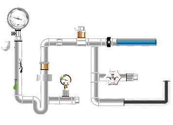
Common hydraulic tube models
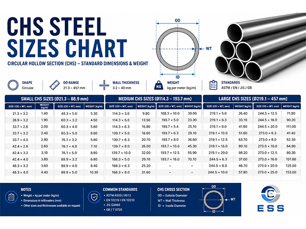
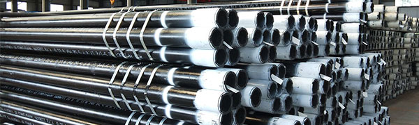
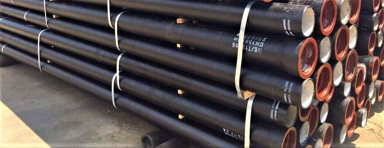
Hydraulic tubes are pipes for conveying hydraulic fluids and are generally made of high-pressure, corrosion-resistant materials. Common hydraulic oil pipe models include the following:
|
Model
|
Pipe diameter (mm)
|
Wall thickness (mm)
|
Maximum operating pressure (MPa)
|
|
GB/T 3639-2009
|
4-120
|
0.5-20
|
25
|
|
JIS G 3455
|
8-114.3
|
1-12
|
32
|
|
EN 10305-4
|
6-42
|
0.5-5
|
16
|
|
ASTM A519
|
15.9-323.8
|
1-20
|
80
|
Note: GB/T indicates national standards, JIS indicates Japanese industrial standards, EN indicates European standards, and ASTM indicates American Society for Testing and Materials standards.
Factors affecting the diameter of hydraulic oil pipes
The diameter of hydraulic oil pipes is one of the key factors affecting the flow rate in hydraulic systems. The main factors affecting it are as follows.
1. Pipeline length: The increase in pipeline length will increase friction, thereby reducing flow rate.
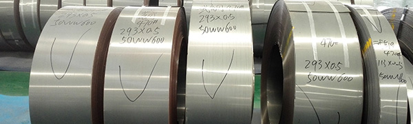
2. Pipe material: The inner wall smoothness of pipes of different materials is different, and the pressure drop will also be different.
3. Number of elbows and bending angles: The greater the number of elbows and bending angles in the pipeline, the greater the pressure drop, so the flow rate will also decrease.
4. Pipe diameter: The smaller the pipe diameter, the smaller the flow rate; the larger the pipe diameter, the greater the flow rate.
Hydraulic oil pipe flow rate
The flow rate of hydraulic oil pipes mainly depends on the size of its inner diameter, the length of the pipe and the viscosity of the fluid. Generally speaking, the flow rate of hydraulic oil pipes can be calculated using the following formula:
Q=πr²v
Where Q is the flow rate in m³/s; π is the circumference; r is the inner diameter of the oil pipe in m; v is the flow rate of the liquid in m/s.
The following table lists the flow rates of commonly used hydraulic oil pipes:
|
Pipe diameter (mm)
|
Flow rate (L/min)
|
|
4
|
0.015
|
|
6
|
0.034
|
|
8
|
0.06
|
|
10
|
0.094
|
|
12
|
0.135
|
|
16
|
0.242
|
|
20
|
0.376
|
Other parameters
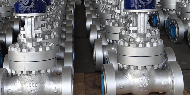
In addition to the above-mentioned pipe diameter, wall thickness, maximum operating pressure and flow rate, there are some other parameters of hydraulic oil pipes that need attention, such as: pressure resistance, wear resistance, bending radius, weight, etc.
Relationship between hydraulic oil pipe diameter and flow rate
1. Flow rate formula
Q=πD²/4×v
In the formula, Q is the flow rate, D is the pipe diameter, and v is the liquid flow rate.
It can be seen that the flow rate is directly proportional to the pipe diameter. When the liquid flow rate is constant, the larger the pipe diameter, the greater the flow rate; when the pipe diameter is constant, the faster the flow rate, the greater the flow rate.
2. Actual impact
In actual applications, factors such as pipeline length, pipe material, number of elbows and bending angles in the hydraulic system cannot be ignored. Therefore, when designing a hydraulic system, the diameter of the hydraulic oil pipe should be comprehensively considered according to the actual situation to obtain the best flow effect.
In short, the diameter of the hydraulic oil pipe is closely related to the flow rate. When designing a hydraulic system, a variety of factors should be considered comprehensively to select the best pipe diameter to achieve the best hydraulic system effect. Different hydraulic oil pipes are suitable for different scenarios and applications. You need to judge and choose according to your specific needs. For most industries and applications, conventional hydraulic oil pipes can already meet the needs.


 Eastern Steel Manufacturing Co.,Ltd not only improve product production and sales services, but also provide additional value-added services. As long as you need, we can complete your specific needs together.