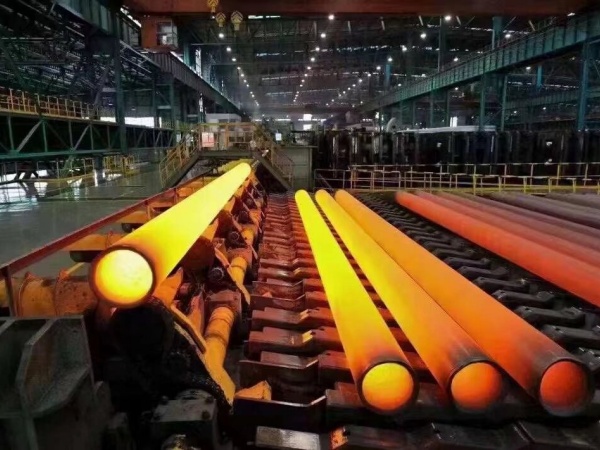
1. Carbon Steel Pipe Roughness Reference
For new commercial carbon steel pipe, the standard absolute roughness value used in engineering calculations is:
ε = 0.045 mm (0.00015 ft)
This value is widely used for Darcy–Weisbach pressure loss calculations, the Moody diagram, and the Colebrook equation. It is also adopted as the reference value in many engineering publications and fluid mechanics references.
Common references:
- Crane Technical Paper No. 410
- Engineering Toolbox
- Moody Diagram
- Colebrook Equation
- Fluid Mechanics textbooks
Note: Actual roughness varies with manufacturing method and service condition. Corrosion, scaling, and internal deposits generally increase pipe roughness over time.
2. Carbon Steel Pipe Roughness Chart (ε Values)
|
Pipe Type
|
Condition
|
Absolute Roughness ε (mm)
|
ε (ft)
|
Relative Roughness ε/D (Typical)
|
|
Precision / Cold-Drawn Steel Pipe
|
Very smooth, new
|
0.015 – 0.03
|
0.00005 – 0.00010
|
0.00005 – 0.0002
|
|
Commercial Steel Pipe (Seamless Pipe/ Welded pipe)
|
New, clean
|
0.045 – 0.15
|
0.00015 – 0.00050
|
0.0002 – 0.001
|
|
Galvanized Steel Pipe
|
New
|
0.15 – 0.20
|
0.00050 – 0.00066
|
0.0005 – 0.0015
|
|
Carbon Steel Pipe (In Service)
|
Slight corrosion / scaling
|
0.2 – 0.5
|
0.00066 – 0.00164
|
0.001 – 0.003
|
|
Old / Corroded Carbon Steel Pipe
|
Heavy scaling / rough surface
|
0.5 – 1.5
|
0.00164 – 0.00492
|
0.003 – 0.01
|
Notes and References :
These values are widely used in engineering calculations based on the Moody diagram and standard fluid mechanics references.
Typical roughness values for commercial steel pipes (ε ≈ 0.045 mm) are consistent with data used in:
- Crane Technical Paper No. 410
- Fluid Mechanics textbooks
Actual roughness may vary depending on:
- Manufacturing process (seamless vs welded)
- Surface treatment (galvanized, coated)
- Operating conditions (corrosion, scaling, erosion)
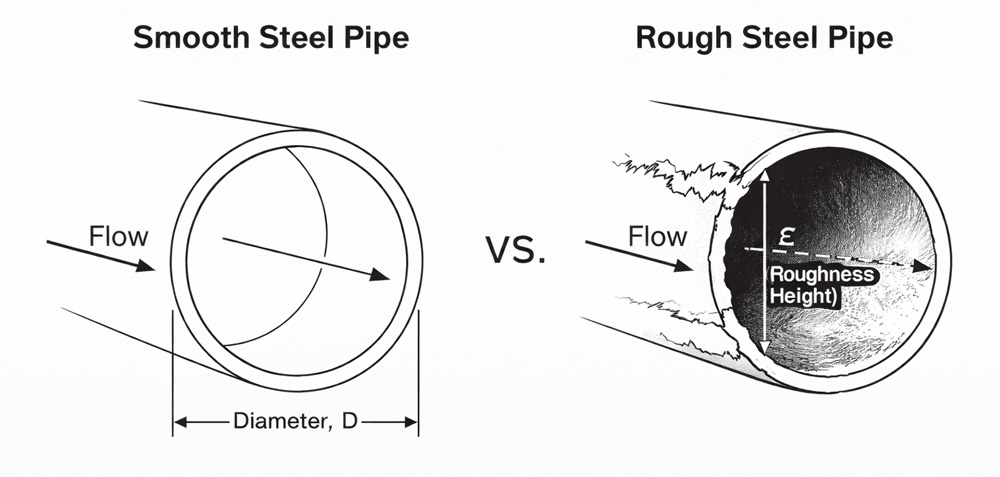
3. Absolute vs Relative Roughness
In pipe flow calculations, roughness can be expressed in two forms: absolute roughness (ε) and relative roughness (ε/D).
3.1 Absolute Roughness (ε)
Absolute roughness (ε) represents the actual height of surface irregularities on the pipe wall.
Unit: mm or ft
Property: depends only on pipe material and surface condition
3.2 Relative Roughness (ε/D)
Relative roughness (ε/D) is the ratio of absolute roughness to the internal pipe diameter.
- Dimensionless (no unit)
- Depends on both pipe roughness and pipe size
- Used directly in friction factor calculations (Moody diagram / Colebrook equation)
3.3 Key Difference
|
Parameter
|
Absolute Roughness (ε)
|
Relative Roughness (ε/D)
|
|
Definition
|
Surface height
|
Ratio of roughness to diameter
|
|
Unit
|
mm / ft
|
Dimensionless
|
|
Depends on
|
Material & condition
|
Material + pipe diameter
|
|
Engineering Use
|
Input parameter
|
Used to determine friction factor
|
For the same pipe material, a smaller diameter results in a higher ε/D value, which leads to greater flow resistance. This is why roughness effects are more significant in small-diameter pipes.
4. Calculation and Engineering Use of Pipe Roughness
In pipeline design, roughness is used to determine the friction factor (f), which directly controls pressure loss.
h₍f₎ = f · (L / D) · (v² / 2g)
The friction factor is a function of Reynolds number and relative roughness (ε/D). For turbulent flow, which is typical in industrial systems, ε/D becomes a controlling parameter.
Values of f are obtained from the Moody diagram or calculated using the Colebrook equation.
As roughness increases, its influence on friction becomes more significant, especially in turbulent flow.
In practical terms, two pipes with the same diameter can produce very different pressure losses if their internal condition differs. A clean carbon steel pipe and a scaled pipe will not behave the same hydraulically.
For this reason, design work typically starts with selecting a representative roughness value based on pipe condition, converting it to ε/D, and then determining f from standard references.
5. Typical Roughness Values by Pipe Condition
Roughness in carbon steel pipe is not constant. It changes with service conditions, mainly due to corrosion, scaling, and deposits.
New pipes have relatively smooth internal surfaces. Cold-drawn or precision tubes are at the lower end of the roughness range, while standard commercial pipes are higher due to manufacturing characteristics. A value of ε = 0.045 mm is commonly used for new carbon steel pipe in design calculations.
During operation, internal surfaces gradually deteriorate. Light corrosion or scaling increases roughness and leads to measurable increases in friction loss.
In older systems, heavy scaling or uneven corrosion can significantly increase roughness. The hydraulic behavior at this stage deviates from standard assumptions, and higher ε values must be used.
6. Why Is the Roughness of Commercial Steel Pipe Usually 0.045 mm?
The commonly accepted roughness value for new commercial carbon steel pipe is ε = 0.045 mm (0.00015 ft).
Engineers use this value as a standard design reference for friction loss calculations based on the Darcy–Weisbach equation, Moody diagram, and Colebrook equation. It is widely cited in engineering references, including Crane Technical Paper No. 410, Engineering Toolbox, and fluid mechanics textbooks.
Actual roughness varies with the manufacturing process and service condition. Precision tubing typically has a smoother internal surface, while corrosion, scaling, and long-term operation increase pipe roughness over time.
7. Carbon Steel Pipe Roughness vs Other Pipe Materials
Different pipe materials have different surface roughness, which directly affects friction loss and pressure drop. In general, smoother materials produce lower flow resistance under the same operating conditions.
Carbon steel pipe — The standard roughness value for new commercial pipe is ε = 0.045 mm, making it the reference material used in most industrial flow calculations.
Stainless steel pipe — Usually has a smoother internal surface than carbon steel, resulting in lower friction loss in clean piping systems.
Galvanized steel pipe — The zinc coating creates a rougher internal surface than bare carbon steel, leading to slightly higher friction factors.
PVC pipe — Has a very smooth internal surface with much lower roughness than steel pipes, making it suitable for low-pressure-loss water systems.
HDPE pipe — One of the smoothest pipe materials. Its low roughness helps maintain stable hydraulic performance over long service periods.
8. FAQs
Q1. What is the standard roughness value for commercial carbon steel pipe?
For new commercial carbon steel pipe, the standard engineering design value is ε = 0.045 mm (0.00015 ft). It is widely used for Darcy–Weisbach calculations and the Moody diagram.
Q2. Does seamless pipe have a lower roughness than welded pipe?
Generally yes. Seamless pipe usually has a more uniform internal surface, while welded pipe may have additional irregularities along the weld seam. The actual roughness still depends on manufacturing quality and service condition.
Q3. Why do engineers use 0.045 mm instead of measuring every pipe?
Because hydraulic system design requires a standard reference value. 0.045 mm represents clean commercial steel pipe and provides consistent pressure-loss calculations without measuring every individual pipe.
Q4. Does pipe roughness increase over time?
Yes. Corrosion, scaling, erosion, and internal deposits gradually increase roughness, resulting in higher friction loss and pressure drop.
Q5. What is the difference between absolute roughness and relative roughness?
Absolute roughness (ε) describes the surface irregularities of the pipe wall. Relative roughness (ε/D) compares that roughness with the pipe diameter and is the value used to determine the friction factor.
Q6. Where is carbon steel pipe roughness used?
It is mainly used in hydraulic calculations, including the Darcy–Weisbach equation, Moody diagram, and Colebrook equation for estimating pressure loss in piping systems.
Read more: Surface Roughness of Carbon Steel Pipe or What Affect The Absolute Roughness of Carbon Steel Pipes





 Eastern Steel Manufacturing Co.,Ltd not only improve product production and sales services, but also provide additional value-added services. As long as you need, we can complete your specific needs together.