Operators commonly check electrical continuity across pipe flanges in systems handling flammable liquids, hydrocarbon gases, and other static-sensitive media where pipe flange static bonding or grounding jumpers are required to ensure equipotential connection.
In many facilities, technicians perform continuity testing after flange assembly, gasket replacement, maintenance shutdowns, or bonding jumper installation to confirm that static charge can safely dissipate through the piping system.
Testing becomes especially important on insulated flange assemblies, PTFE gasket connections, painted piping, and systems exposed to corrosion or repeated dismantling.
1. Standards Referenced for Flange Continuity Testing
Several industrial standards reference bonding and conductive continuity for piping systems handling flammable media.
API RP 2003 is widely used in petroleum facilities and hydrocarbon transfer systems. It covers electrostatic ignition control during loading, unloading, storage, and product transfer operations.
NFPA 77 includes recommendations for bonding conductive equipment, piping assemblies, transfer systems, and metallic components where static accumulation may occur.
In hazardous-area installations associated with IEC 60079 practices, conductive continuity is commonly considered during grounding and equipment installation, especially around isolated metallic sections and non-conductive connections.
Many facilities also apply internal continuity inspection procedures during flange installation, gasket replacement, maintenance shutdowns, and turnaround work.
2. Design and Installation Conditions Affecting Continuity
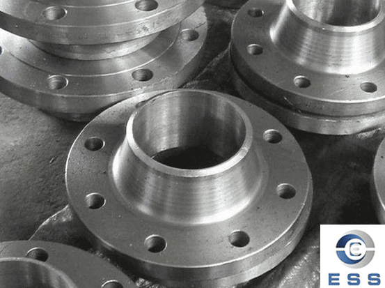
Electrical continuity across pipe flanges can be affected by design and installation-related factors that interrupt direct metal-to-metal contact.
Common conditions include insulated flange gasket systems, PTFE gasket assemblies, painted flange faces, and coating layers at the contact surface. These elements are often intentionally used for corrosion protection, process isolation, or electrical separation between piping sections.
In such configurations, flange contact surfaces may not provide reliable conductive paths, and continuity cannot be assumed without verification or supplemental bonding measures.
3. Field Degradation and Failure Mechanisms
Even in systems originally designed for good metal-to-metal contact, electrical continuity can deteriorate over time due to field operating conditions.
Typical degradation mechanisms include corrosion development at flange faces or bolts, vibration-induced loosening of bolted joints, contamination from oil, dirt, or sealant materials, and long-term increases in contact resistance due to surface aging or oxidation.
These factors may cause initially conductive flange connections to exhibit unstable or high-resistance readings during field continuity testing, even when mechanical tightness appears acceptable.
4. How Is Continuity Tested Across a Flange?
Continuity across a flange connection is commonly checked using a digital multimeter or low-resistance ohmmeter.
During field inspection, test probes are typically placed on opposite sides of the flange assembly to verify that electrical resistance remains within the facility's acceptable range.
Testing is often performed after flange assembly, gasket replacement, maintenance shutdowns, or installation of insulating flange kits and bonding jumpers.
In hazardous-area piping systems, continuity checks may also be included as part of periodic grounding and static-control inspections.
5. Recommended Continuity Resistance Values
In industrial grounding and static control practices, electrical continuity across pipe flange connections is commonly expected to remain below 10 ohms under normal operating conditions.
In hydrocarbon processing, loading terminals, and other hazardous-area piping systems, some facilities adopt stricter internal limits to ensure higher reliability of static dissipation and bonding performance.
Where insulating gaskets, flange isolation kits, or non-conductive coatings are intentionally used, electrical continuity may be interrupted by design. In such cases, continuity is not expected across the flange, and external bonding jumpers are typically applied to maintain static discharge control while preserving system isolation requirements.
Read more: Material And Features of Loose Flange or Flange sealing surface finish requirements





 Eastern Steel Manufacturing Co.,Ltd not only improve product production and sales services, but also provide additional value-added services. As long as you need, we can complete your specific needs together.