Research on sealing performance of OCTG casing connection
With the development of deep wells, ultra-deep wells, high-pressure oil and gas wells, heavy oil thermal recovery wells, heavy corrosion wells, directional wells, etc., increasingly stringent technical requirements have been put forward for oil casing. According to statistics, the joint is the weakest link in the entire pipe string; therefore, the performance of the joint directly determines the performance of the oil casing product and even the entire pipe string.

Due to the plastic deformation of special thread joint materials, the complexity of the contact of special thread structures and the diversity of load conditions, it is difficult to use analytical methods to describe the joint sealing integrity problem; therefore, it is necessary to use finite element numerical simulation software to realize special thread joints Seal reliability analysis. In recent years, domestic and foreign scholars and technicians have applied finite element analysis technology to air sealing evaluation, fatigue design, strength analysis and other aspects of special threads. XIE et al. used the finite element method to study the structural integrity and sealing capabilities of API casing and special threaded casing under the cyclic load of thermal recovery wells. Comparative analysis showed that special threads are most suitable for thermal recovery wells. Dou Yihua et al. used the three-dimensional finite element method to analyze the impact of different make-up torques on the torque curve and contact pressure distribution of special threaded joints. These studies provide good guidance for the development of new threaded oil and casing pipes, but there are not many systematic simulation evaluations of the special thread performance of oil and casing pipes in accordance with the test content and procedures of the ISO13679:2002 standard.
This article takes a special threaded joint of 177.8 mmx10.36 mm oil casing in P110 steel grade as the analysis object, based on the test procedures and methods of ISO13679:2002 standard CAL II and sealing contact energy theory, combined with finite element simulation analysis and physical evaluation Test to comprehensively evaluate the sealing performance of this special threaded joint.
1. Finite element analysis of sealing performance of special threaded joints
1.1 Research objects
Taking a special thread as the research object, its geometric structure is shown in Figure 1. This special threaded joint mainly consists of three parts: threaded part, sealing surface and shoulder. Among them, the sealing surface adopts the sealing form of spherical surface with metal interference on the cone surface. This sealing form has the advantages of long upper buckle and sliding distance, high average contact pressure, low local pressure and long contact length. The shoulder adopts a right-angle structure, which is convenient for processing and achieves sealing by its own interference contact14. The threaded connection form is BJC-I type. The yield strength of oil casing is 762MPa, the tensile strength is 913 MPa, the elastic modulus is 210 GPa, the friction factor is 0.025, and the Poisson's ratio is 0.3.
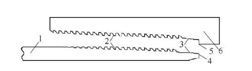
1-Pipe body 2-BJC-I thread 3-Metal seal 4-Top of casing 5-Shoulder 6-Coupling
Figure 1 Schematic diagram of the geometric structure of a special thread
1.2 Theoretical analysis
The purpose of the load envelope test in the ISO 13679:2002 standard is to evaluate whether the structural integrity and sealing performance of special threaded joints can be guaranteed under the maximum load or combined load in actual safe use. The composite load envelope is calculated using the Von Mises strain energy theory, which points out the yield phenomenon during composite loading and can be calculated using a single principal stress according to formulas (1)~(4).
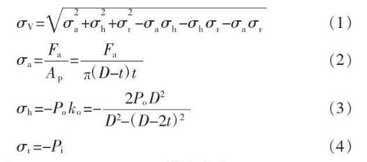
in the formula
σ
v——Von Mises equivalent stress, MPa;
σ
a——axial stress, MPa;
σ
h—— hoop stress, MPa;
σ
r——radial stress, MPa;
F
a—— total axial load, kN;
D——tube outer diameter, mm;
t—— pipe body wall thickness, mm;
A
p——Pipe body cross-sectional area, mm
2;
P
0——external pressure, MPa;
K
0——geometric constant;
P
i——internal pressure, MPa.
The test load envelope of the special threaded joint of oil and casing is shown in Figure 2.
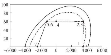
Y: Internal pressure/MPa
X: load/kN (-6000~0: compression; 0~6000: tension)
—: 100% envelope ﹍: 85% envelope ﹎: Test load line
Figure 2 Test load envelope of special threaded joints for oil and casing
According to the ISO 13679:2002 standard, a finite element analysis of the threaded joints was first performed on the special threaded joints to evaluate whether the threads would stick during the threading process, which would lead to a reduction in the strength of the threaded connection, damage to the thread sealing surface, and a decrease in sealing performance; then Conduct load envelope test finite element analysis on special threaded joints to evaluate their structural integrity and sealing performance under compound loads.
1.3 Establishment of finite element model
It is assumed that the pipe body and coupling are both ideal circular pipes, the pipe body and coupling are both linear strengthening models, and the constitutive models of both are the actual stress-strain curves of the material.
When using ABAQUS software, the 3D model of the special threaded joint is simplified into a flat 2D model for analysis to improve calculation efficiency. Axisymmetric units are used for both the pipe body and the coupling, with 77,655 internal thread units and 78,004 nodes; 124,871 external thread units and 125,924 nodes. Symmetry constraints are imposed on the bottom of the tube in the Y direction. The top is applied with tensile, compressive loads and internal pressure consistent with the actual working conditions of the oil field. The finite element mesh division is shown in Figure 3.
1.4 Calculation results and analysis
Sample No. 1, which has the smallest make-up torque and is most likely to leak in the composite loading test, was selected for load analysis under actual oilfield conditions.
1.4.1. Buck-up analysis
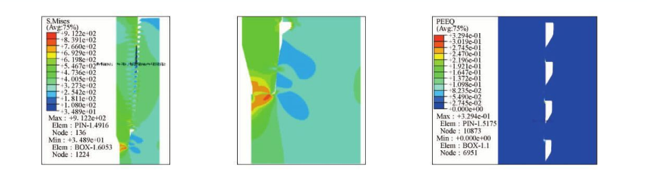
It can be seen from the stress-strain cloud diagram of the screw thread and sealing surface (Figure 4): After the screw-up of sample No. 1 is completed, the maximum equivalent stress
The penultimate tooth top located on the coupling has a maximum equivalent stress of 765MPa; the equivalent stress distribution at the sealing surface is relatively uniform, both around 510 MPa, which does not exceed the yield strength of the material; the equivalent plastic strain distribution is equal to The position of the effect force is the same and its maximum value is 0.002 5%.
1.4.2 Tensile load
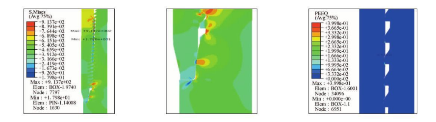
Due to the large load in actual working conditions, the most severe tensile load point was selected for analysis. The stress-strain cloud diagram of the thread and sealing surface after loading 95% tensile load is shown in Figure 5.
It can be seen from Figure 5: After the No. 1 sample with a wall thickness of 10.36mm is buckled and loaded with 95% of the tensile load, the maximum equivalent stress is located at the penultimate tooth top on the coupling, and the maximum equivalent stress is The effective stress is 913.7 MPa; the equivalent stress distribution at the sealing surface is relatively uniform, all around 764MPa, which does not exceed the yield strength of the material; the equivalent plastic strain distribution is the same as the equivalent stress position, and its maximum value is 0.399%.

(a) External thread (b) Internal thread (c) Sealing surface and shoulder
Figure 3 Finite element meshing
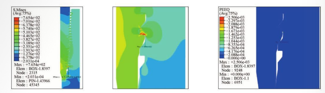
(a) Equivalent stress of thread and sealing surface (b) Equivalent stress of sealing local area (c) Equivalent plastic strain of thread and sealing surface
Figure 4 Stress-strain cloud diagram of the thread and sealing surface
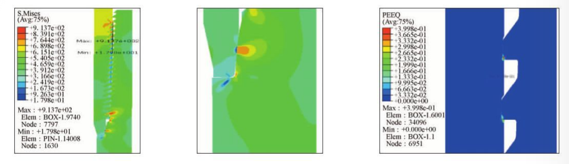
(a) Equivalent stress of thread and sealing surface (b) Equivalent stress of sealing local area (c) Equivalent plastic strain of thread and sealing surface
Figure 5 Stress-strain cloud diagram of the thread and sealing surface after loading 95% tensile load
1.4.3 Compression load
The stress-strain cloud diagram of the thread and sealing surface after loading 60% compressive load is shown in Figure 6. It can be seen from Figure 6: After 60% pressure is loaded on the No. 1 sample with a wall thickness of 10.36mm, the maximum equivalent stress is located at the middle tooth top of the coupling. The maximum equivalent stress is 912MPa. Compared with the wall thickness: 9.19mm is larger; the equivalent stress distribution at the sealing surface is relatively uniform, all around 619.8 MPa, which does not exceed the yield strength of the material; the equivalent plastic strain distribution is the same as the equivalent stress position, and its maximum value is 0.329%.
1.4.4 Tensile load and internal pressure.
The stress-strain cloud diagram of the thread and sealing surface after loading 95% tensile load + internal pressure of 60 MPa is shown in Figure 7. It can be seen from Figure 7: When No. 1 specimen is loaded with 95% tensile load + internal pressure of 60 MPa, the maximum equivalent stress is located at the penultimate tooth top of the coupling, and the maximum equivalent stress is 913.7 MPa. ; The equivalent stress distribution at the sealing surface is relatively uniform, all around 764 MPa, which does not exceed the yield strength of the material; the equivalent plastic strain distribution is the same as the equivalent stress position, with a maximum value of 0.399%.
1.4.5 Quantitative analysis of sealing surface
For the sealing surface of key parts, the relationship between the force on the sealing surface and the contact length of the contact surface after the key points of the special threaded joint are buckled and loaded is analyzed, as shown in Figure 8.
(a) Equivalent stress of thread and sealing surface (b) Equivalent stress of sealing local area (c) Equivalent plastic strain of thread and sealing surface
Figure 6 Stress-strain cloud diagram of thread and sealing surface after loading 60% compressive load
(a) Equivalent stress of thread and sealing surface (b) Equivalent stress of sealing local area (e) Equivalent plastic strain of thread and sealing surface
Figure 7 Stress-strain cloud diagram of the thread and sealing surface after loading 95% tensile load + internal pressure 60 MPa
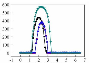
X: sealing surface contact length/mm
Y: sealing surface contact pressure/MPa
Black: After buckling Red: 95% stretch Blue: 60% compression Green: 95% stretch + internal pressure
Figure 8 Comparison of the relationship between sealing surface contact pressure and sealing surface contact length at different stages.
After buckling, the contact pressure of the pipe body begins to increase when the contact length is 1.2 mm, and reaches the maximum when the contact length is 2.0 mm, with a maximum value of 438 MPa. As the contact length increases, the contact pressure gradually decreases, and when the contact length is 2.8 mm, the contact pressure is 25.6 MPa. The entire contact length is 1.2~2.8mm.
After loading 95% tensile load, the contact pressure of the pipe body begins to increase when the contact length is 1.7 mm, and reaches the maximum when the contact length is 2.3 mm, with a maximum value of 379 MPa. As the contact length increases, the contact pressure gradually decreases, and when the contact length is 2.9 mm, the contact pressure is 137.1 MPa. The entire contact length is 1.7~2.9 mm.
After loading 60% compressive load, the contact pressure of the pipe body begins to increase when the contact length is 1.5 mm, and reaches the maximum value of 441.8 MPa when the contact length is 2.2 mm. As the contact length increases, the contact pressure gradually decreases, and when the contact length is 2.9 mm, the contact pressure is 96.3 MPa. The entire contact length is 1.5~2.9 mm. The results of the finite element analysis of the special threaded joint during the top-shackle and load envelope tests showed that the equivalent stress distribution of the special threaded joint under the action of the top-shackle and composite load was relatively uniform and did not exceed the yield strength of the material. , there will be no structural failure or leakage, proving that this special threaded joint can maintain good connection strength and reliable air sealing performance under composite load conditions.
2. Physical evaluation test
2.1 Test methods
Conduct physical evaluation tests on selected special thread limit specimens according to ISO 13679: 2002 standard CALⅡ. The physical evaluation test sample number and test purpose are shown in Table 1. Among them, the No. 1 limit sample is a sealed low-interference sample with the smallest make-up torque and is most likely to leak in the composite loading test; the No. 4 limit sample is a sealed high-interference sample with the largest make-up torque and is most likely to leak. Thread sticking occurred during the upper shackle test. Therefore, limit samples No. 1 and No. 4 were selected for testing. The technical route of the physical evaluation test is shown in Figure 9.
2.2. Top shackle performance evaluation test
According to ISO 13679: 2002 standard CALⅡ, the top and bottom buckle test is carried out on the limit specimen. Since the No. 4 limit sample is a sealed high-interference sample, the external thread sealing surface often undergoes slight plastic deformation during the top-off test; during the top-off test, the joint ovality will change under the action of the clamping force. , the lower the supporting position of the back clamp is, the smaller the ovality of the joint is. The influence of the clamping position of the back clamp on the ovality of the joint is shown in Figure 10. By adjusting the clamping force and the clamping position of the back clamp, the problem of slight plastic deformation of the shackle on the sealing surface of No. 4 ultimate specimen was solved.
|
Table 1 Physical evaluation test sample number and test purpose
|
|
Sample No
|
Test purposes
|
Conditions for deduction
|
Thread interference
|
Seal interference
|
External thread taper
|
Internal thread taper
|
Final torque
|
|
1
|
Sealing performance
|
Minimum sealing interference
|
Low
|
Low
|
Slow
|
Steep
|
Minimum
|
|
2
|
Sealing performance
|
Maximum shoulder torque
|
Low
|
Low
|
Slow
|
Steep
|
Maximum
|
|
3
|
Sealing performance
|
Maximum machine tightness
|
High
|
High
|
Normal
|
Normal
|
Maximum
|
|
4
|
Sealing surface thread bonding trends and sealing performance
|
Maximum sealing interference
|
Low
|
High
|
Steep
|
Slow
|
Maximum
|
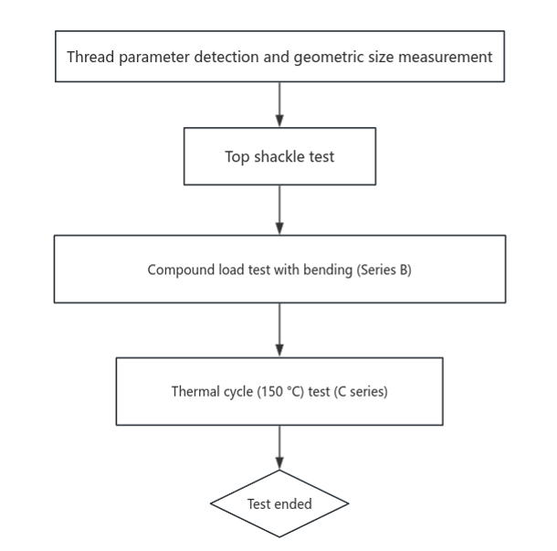
Figure 9 Physical evaluation test technical route
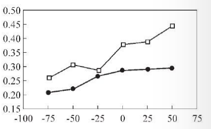
X: clamping position/mm
Y: ellipticity/%
Upper: Clamping force 9.5 MPa Lower: Clamping force 6.5 MPa
Figure 10 The effect of the clamping position of the back clamp on the ovality of the joint
The sample_top shackle test result data is shown in Table 2, and the morphology after top shackle is shown in Figure 11. The results show that no thread adhesion occurred in specimens No. 1 and No. 4 during the upper shackle test, and they meet the requirements of relevant standards. The ratio of the ultimate specimen shoulder torque to the buckle torque is 0.33~0.60. Among them, the ratio of sample No. 1 is relatively low, which is mainly due to the smaller interference of the thread and seal of sample No. 1; the ratio of sample No. 4 is higher, mainly due to the smaller interference of the thread and seal of sample No. 4. big.
|
Table 2 Results of shackle test on specimen
|
|
Sample No
|
Number of shackles
|
Clamping torque/(N.m)
|
Shoulder torque/(N.m)
|
Shoulder torque/Buckle torque
|
Test results
|
|
External thread
|
Internal thread
|
|
1-A
|
1-CA
|
1
|
20056
|
7220
|
0.36
|
-
|
|
1-B
|
1-CB
|
1
|
23187
|
7652
|
0.33
|
Threads not bonded
|
|
2
|
23187
|
8795
|
0.38
|
Threads not bonded
|
|
3
|
23223
|
9521
|
0.41
|
-
|
|
4-A
|
4-CA
|
1
|
23150
|
13996
|
0.60
|
-
|
|
4-B
|
4-CB
|
1
|
23469
|
13115
|
0.56
|
Threads not bonded
|
|
2
|
23250
|
12905
|
0.56
|
Threads not bonded
|
|
3
|
23156
|
13340
|
0.58
|
-
|
2.3 Load envelope test
According to the requirements of ISO 13679:2002 standard CAL II, the load envelope test was carried out on the limit specimens No. 1 and 4, and the tensile/compression and internal pressure tests under bending conditions (B series test), as well as the tensile and internal pressure tests were carried out successively. Thermal cycle test under pressure (C series test). The load envelope test load points are shown in Table 3.
Through experimental observation, during the entire load envelope test process, no structural failure or leakage occurred in the No. 1 and No. 4 limit specimens, proving that this special threaded joint can maintain good connection strength and reliable performance under composite load conditions. Air sealing performance.
3.Conclusion
(1) Through the finite element analysis of the top shackle and load envelope test process of this special threaded joint, the equivalent stress distribution under the action of the top shackle and composite load is relatively uniform and does not exceed the yield strength of the material. There will be no structural failure or leakage, proving that this special threaded joint can maintain good connection strength and reliable air sealing performance under composite load conditions.
(2) Through physical evaluation of the No. 1 and No. 4 limit specimens of the special threaded joint, no structural failure or leakage occurred during the entire upper shackle and load envelope test, proving that the special threaded joint has Good connection strength and reliable air sealing performance can be maintained under composite load conditions.
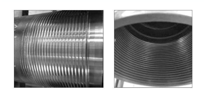
(a) After the B end is buckled once and once removed (b) After the CB end is buckled twice and removed twice
Figure 11 Sample No. 1. Morphology after shackle
|
Table 3 Load envelope test load points.
|
|
loading point
|
Axial mechanical load/kN
|
Total axial load/kN
|
Internal pressure/MPa
|
Dog leg bending degree/[(°).(30 m)-1]
|
Test temperature/℃
|
Hold time/
min
|
VME envelope/%
|
|
1
|
3512
|
3512
|
0
|
0
|
Room temperature
|
5
|
85.0
|
|
2
|
2382
|
3544
|
60
|
0
|
Room temperature
|
15
|
85.0
|
|
3
|
1352
|
3544
|
60
|
20
|
Room temperature
|
15
|
85.0
|
|
4
|
-1163
|
0
|
60
|
0
|
Room temperature
|
15
|
68.5
|
|
5
|
-1352
|
-1219
|
60
|
20
|
Room temperature
|
15
|
85.0
|
|
6
|
-2382
|
-1219
|
60
|
0
|
Room temperature
|
15
|
85.0
|
|
7
|
-2478
|
-2478
|
0
|
0
|
Room temperature
|
15
|
60.0
|
(3) Taking a special threaded joint as the analysis object, based on the ISO13679:2002 standard, the sealing performance of the special threaded joint is evaluated through the finite element method, and compared with the physical test results, it is proved that the special threaded joint can operate under the composite load condition It can maintain good connection strength and reliable air sealing performance. This evaluation method is an effective method to evaluate the sealing performance of special threaded joints, and provides a basis for subsequent research, design, selection and optimization.
Read more: The causes of OCTG casing stuck or Research on basic properties of steel used in OCTG casing


 Eastern Steel Manufacturing Co.,Ltd not only improve product production and sales services, but also provide additional value-added services. As long as you need, we can complete your specific needs together.