Pressure loss in hydraulic tubes includes
friction loss, local pressure loss, and total pressure loss. Friction loss is
caused by friction and resistance, while local loss is caused by pipe bends,
joints, etc. To reduce pressure loss, measures such as increasing pipe
diameter, reducing the number of bends and joints, and increasing fluid
temperature can be taken.
Pressure loss in hydraulic tubes is a
common problem in hydraulic systems, which can lead to reduced system
efficiency and even affect the normal operation of equipment. So, what are the
different types of pressure loss in hydraulic tubes?
Types of Pressure Loss in Hydraulic Tubes
1. Friction Loss
Friction loss refers to the pressure
reduction caused by friction and resistance as the fluid flows in the hydraulic
tube. This loss is related to the pipe length, inner diameter, material, and
the properties and flow rate of the fluid. This is generally expressed as a
pressure drop, called the friction loss ΔPλ, and is calculated using the following formula:

Where, λ—friction
coefficient, a function of Reynolds number Re and relative roughness Δ/d;
l—length of the
pipe along the friction path, m;
d—inner diameter of
the pipe, m;
v—average velocity
inside the pipe, m/s;
ρ—fluid density, kg/m³.
|
Hydraulic Tube Material
|
Inner Wall Condition
|
Absolute Roughness Δ/mm
|
|
Copper
|
Cold-drawn copper tube, brass tube
|
0.0015~0.01
|
|
Aluminum
|
Cold-drawn aluminum tube, aluminum alloy
tube
|
0. 0015~0.06
|
|
Steel
|
Cold-drawn seamless steel tube
|
0.01~0.03
|
|
Hot-drawn seamless steel tube
|
0.05~0.1
|
|
Rolled seamless steel tube
|
0.05~0.1
|
|
Galvanized steel tube
|
0.12~0.15
|
|
Asphalt-coated steel tube
|
0. 03~0.05
|
|
Corrugated pipe
|
0.75~7.5
|
|
Cast iron
|
Cast iron tube
|
0.05
|
|
Plastic
|
Smooth plastic tube
|
0.0015~0.01
|
|
Corrugated pipe with d=100mm
|
5~8
|
|
Corrugated pipe with d>200mm
|
15~30
|
|
Rubber
|
Smooth rubber tube
|
0.006~0.07
|
|
Rubber hose containing reinforcing steel
wire
|
0.3~4
|
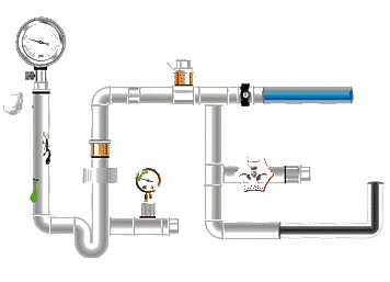
2. Local pressure loss
Local pressure loss refers to the pressure
reduction caused by changes in fluid direction, velocity, and collisions as the
fluid flows through elbows, joints, valves, and other local resistance
components in a hydraulic tube. This loss is related to the type, number, and
installation location of the resistance components. Overcoming local resistance
requires energy, generally manifested as a pressure drop.

In the formula, ξ—local
resistance coefficient, which is related to the shape of the pipe fitting and
the Reynolds number;
v—average flow
velocity, m/s, generally refers to the average velocity on the flow
cross-section after the local pipe fitting unless otherwise specified.
3. Total pressure loss
Total pressure loss is the sum of friction
loss and local pressure loss. It is one of the important indicators for
evaluating the performance of a hydraulic system.

Causes of Pressure Loss in Hydraulic Piping
Pressure loss in hydraulic piping is mainly
caused by factors such as fluid viscosity, friction of the pipeline inner wall,
fluid velocity changes, and fluid turbulence. In addition, local resistance
components such as bends, joints, and valves in the pipeline can also impede
fluid flow, leading to pressure loss. The following is an analysis of key
factors:
1. Fluid Properties
Viscosity: High-viscosity fluids (such as
heavy-duty hydraulic oil) have greater frictional resistance and higher
pressure loss. For example, ISO VG 46 hydraulic oil has a viscosity of 46 cSt
at 40°C, and its pressure loss is about 15%-20% higher
than that of low-viscosity oils.
Temperature: Increased temperature reduces
viscosity, thus reducing pressure loss. However, excessively high temperatures
may lead to oil oxidation, requiring balanced control.
2. Pipeline Design
Pipe Diameter: The smaller the diameter of
the hydraulic tube, the higher the flow velocity and the greater the pressure
loss. According to the Darcy-Weisbach equation, pressure loss is inversely
proportional to the fifth power of the pipe diameter.
Pipeline Length: Long hydraulic tubes
increase friction loss; the design should aim to shorten the pipeline as much
as possible or use segmented pressure reduction.
3. Flow Velocity and Flow Rate
Excessively high flow velocities exacerbate
turbulence, significantly increasing pressure loss. A flow rate of 2-6 m/s is
generally recommended, with lower values used for
high-pressure systems.
Sudden changes in flow rate (such as pump
start-up and shutdown) can cause instantaneous pressure fluctuations, which
need to be mitigated by accumulators or buffer valves.
4. Hydraulic Component Types and Layout
Valves: Components such as throttle valves
and directional valves introduce localized losses. For example, the pressure
loss of a typical check valve is approximately 0.1-0.3 MPa.
Layout Optimization: Reducing the number of
bends and using large-radius bends (R/D ≥ 1.5) can
reduce losses.
Common Values of Hydraulic System Pressure Loss
Based on practical experience and
theoretical research, common values for hydraulic system
pressure loss are typically between 10% and 30%. This range is based on the
combined effects of multiple factors.
Measures to Reduce Hydraulic Line
Pressure Loss
To reduce hydraulic line pressure loss, the
following measures can be taken:
1. Increase line diameter. Increasing the line diameter reduces fluid
velocity and frictional resistance, thereby reducing pressure loss along the
flow path.
2. Reduce the number of elbows and joints.
Reducing the number of elbows and joints can decrease fluid turbulence and
collision effects, thereby reducing local pressure loss.
3. Increase the fluid temperature.
Increasing the fluid temperature can reduce fluid viscosity and frictional
resistance, thereby reducing pressure loss along the flow path. However, it
should be noted that excessively high temperatures may affect fluid stability
and sealing performance.
Summary
Hydraulic tube pressure loss is a core
factor affecting the efficiency, energy consumption, and reliability of
hydraulic systems. It essentially stems from frictional losses along the flow
path and local resistance losses. In engineering practice, by appropriately selecting
pipe diameters, controlling flow rates, optimizing pipeline layout, and using
low-roughness, high-quality hydraulic tubes, system pressure loss can typically
be controlled within 10%, significantly improving system performance.


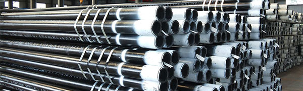
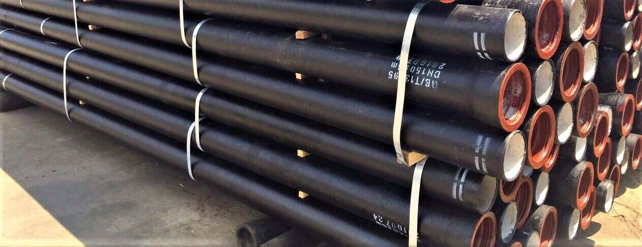


 Eastern Steel Manufacturing Co.,Ltd not only improve product production and sales services, but also provide additional value-added services. As long as you need, we can complete your specific needs together.