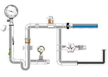
Hydraulic tubes can be divided into two
categories according to different materials: iron hydraulic tubes and non-iron
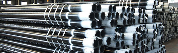
hydraulic tubes. Iron hydraulic tubes are divided into seamless
pipes and welded
pipes, and non-iron hydraulic tubes mainly include nylon pipes, polyester
pipes, polyurethane pipes, corrugated pipes, etc.
Common materials for hydraulic tubes
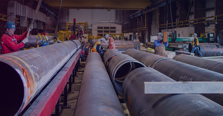
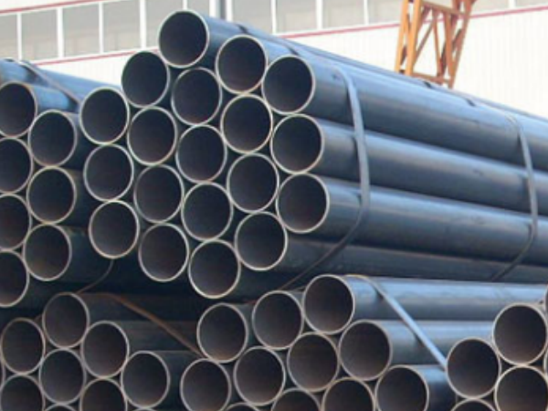
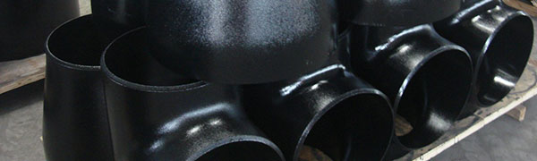
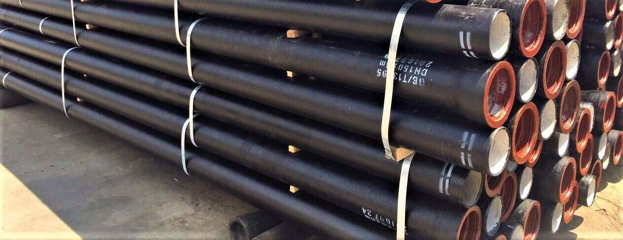
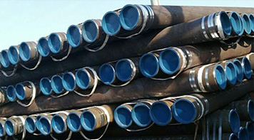
1. Iron hydraulic tubes
Cold-drawn seamless steel pipes, welded
steel pipes, cast iron pipes, etc.
2. Non-iron hydraulic tubes
Nylon pipes, polyester pipes, polyurethane
pipes, corrugated pipes, etc.
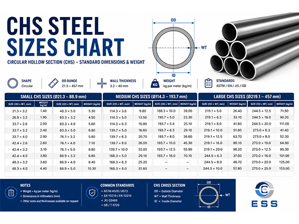
Common hydraulic tube diameter parameter
chart
The following is a common hydraulic tube
diameter parameter table for reference only:
1. Iron seamless pipe
|
Pipe diameter(mm)
|
Inner diameter(mm)
|
Outer diameter(mm)
|
Wall thickness(mm)
|
|
4
|
2.3
|
4
|
0.85
|
|
5
|
3.3
|
5
|
0.85
|
|
6
|
4.3
|
6
|
0.85
|
|
8
|
6.5
|
8
|
0.75
|
|
10
|
8.5
|
10
|
0.75
|
|
12
|
10.5
|
12
|
1
|
|
14
|
12.5
|
14
|
1
|
|
16
|
14.5
|
16
|
1
|
|
18
|
16.5
|
18
|
1
|
|
20
|
18.5
|
20
|
1
|
2. Iron welded pipe
|
Pipe diameter(mm)
|
Inner diameter(mm)
|
Outer diameter(mm)
|
Wall thickness(mm)
|
|
6
|
5.4
|
6.5
|
0.55
|
|
8
|
7.4
|
8.5
|
0.55
|
|
10
|
9.3
|
10
|
0.35
|
|
12
|
11.2
|
12.5
|
0.65
|
|
14
|
13.1
|
14
|
0.45
|
|
16
|
14.9
|
16
|
0.55
|
|
18
|
16.7
|
18
|
0.65
|
|
20
|
18.5
|
20
|
0.75
|
|
22
|
20.3
|
22
|
0.9
|
|
25
|
23
|
25
|
1
|
3. Nylon hose
|
Pipe diameter(mm)
|
Inner diameter(mm)
|
Outer diameter(mm)
|
|
4
|
2.5
|
4
|
|
6
|
4
|
6
|
|
8
|
5.5
|
8
|
|
10
|
7
|
10
|
|
12
|
9
|
12
|
|
14
|
10.5
|
14
|
|
16
|
12
|
16
|
|
18
|
13.5
|
18
|
|
20
|
15
|
20
|
4. Polyester tube
|
Pipe diameter(mm)
|
Inner diameter(mm)
|
Outer diameter(mm)
|
|
6
|
4
|
6
|
|
8
|
5.5
|
8
|
|
10
|
7
|
10
|
|
12
|
9
|
12
|
|
14
|
11
|
14
|
|
16
|
13
|
16
|
|
18
|
15
|
18
|
|
20
|
16
|
20
|
5. Polyurethane tube
|
Pipe diameter(mm)
|
Inner diameter(mm)
|
Outer diameter(mm)
|
|
4
|
2.5
|
4
|
|
6
|
4
|
6
|
|
8
|
5.5
|
8
|
|
10
|
7
|
10
|
|
12
|
9
|
12
|
|
14
|
11
|
14
|
|
16
|
12
|
16
|
|
18
|
13.5
|
18
|
|
20
|
15
|
20
|
6. Bellows
|
Pipe diameter(mm)
|
Inner diameter(mm)
|
Outer diameter(mm)
|
|
6.3
|
4.5
|
6.3
|
|
8
|
6
|
8
|
|
10
|
7.5
|
10
|
|
13
|
10
|
13
|
|
16
|
12.5
|
16
|
|
19
|
15
|
19
|
|
22
|
18
|
22
|
|
25
|
21
|
25
|
The above is only a table of common
hydraulic tube diameter parameters. According to different hydraulic system
requirements and working conditions, parameters such as pipe diameter need to
be considered comprehensively. It is recommended that when designing and
maintaining hydraulic systems, appropriate pipe diameters and materials should
be selected according to actual conditions.
How to determine the diameter of
hydraulic tubes
1. Liquid flow calculation
Liquid flow is the basis for selecting the
diameter of hydraulic tubes in hydraulic systems. In hydraulic system design,
it is generally necessary to know the flow rate of the liquid. By calculating
the flow rate of the liquid, the size of the pipe and parameters such as flow
rate can be determined. The calculation formula for liquid flow is as follows:
Q=πd²/4*v
Where Q represents flow rate, d represents
pipe diameter, and v represents flow rate. According to the formula, the
relationship between pipe diameter and flow rate is inversely proportional,
that is, the larger the pipe diameter, the smaller the flow rate; the smaller
the pipe diameter, the greater the flow rate.
2. Working pressure calculation
The working pressure of the hydraulic tube
in the hydraulic system is also one of the key factors in selecting the
internal size of the pipe. The working pressure of the hydraulic tube depends
on the maximum working pressure in the system. Usually, designers use the
highest working pressure in the hydraulic system as the working pressure of the
hydraulic tube. When calculating the design pressure of the pipeline, it is
necessary to take the working pressure as the basis and consider factors such
as shock waves and temperature changes that may occur in the system.
3. Flow rate calculation
The flow rate of the pipeline is also an
important parameter for designing the diameter of the hydraulic tube. It can be
calculated by the following formula:
v=Q/πd²/4
Wherein, v represents the flow rate, d
represents the pipe diameter, and Q represents the flow rate. Generally
speaking, the flow rate is preferably 5 to 8 meters per second. Too high or too
low will affect the normal operation of the hydraulic system.
Conclusion
The selection of materials and pipe
diameter of hydraulic tubes is crucial to the normal operation of hydraulic
systems. When designing and maintaining hydraulic systems, various factors
should be considered comprehensively to select appropriate materials and pipe
diameters. To determine the diameter of the hydraulic tube, it is necessary to
comprehensively consider factors such as liquid flow, working pressure and flow
rate, select appropriate pipe specifications and materials, and ultimately
ensure the normal and safe operation of the system.
Read more: Seamless Steel Pipe Size Chart – OD, Wall Thickness


 Eastern Steel Manufacturing Co.,Ltd not only improve product production and sales services, but also provide additional value-added services. As long as you need, we can complete your specific needs together.