ERW high frequency welding process and quality control
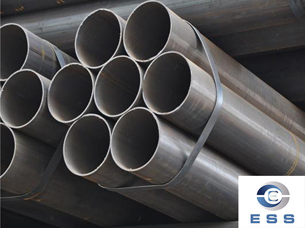
High-frequency welding originated in the 1950s. It is a new welding process that uses the skin effect and adjacent effect generated by high-frequency current to join steel plates and other metal materials. The emergence and maturity of high-frequency welding technology has directly promoted the huge development of the straight seam
welded pipe industry. It is a key process in the production of
ERW pipe. The quality of high-frequency welding directly affects the overall strength, quality level and production speed of welded pipe products.
The production process of high-frequency welded pipes mainly depends on the product variety. From raw materials to finished products, a series of processes are required. Completing these processes requires corresponding various mechanical equipment and welding, electrical control, and testing devices. These equipment and devices are based on different processes. The process requires a variety of reasonable arrangements. As a welded pipe manufacturer, you must have a deep understanding of the basic principles of high-frequency welding, the structure and working principles of high-frequency welding equipment, and the key points of high-frequency welding quality control.
Typical process of high frequency welded pipe:
Loading - Inspection - Shearing and Butt Welding - Looper Storage - Forming - High Frequency Welding - Burr Removal - Cooling - Flaw Detection - Sizing and Straightening - Flying Cutting - Intermediate Inspection - Extracting Internal Burrs - Flat Head Chamfering - Packing and Warehousing .
1. Loading inspection (uncoiling)
1.1 Before and after decoiling, the steel grade or grade of the narrow strip steel should be checked, and the equipped measuring tool should be used to randomly check (at least once/one large steel coil) that the specifications (width × thickness) comply with the steel grade or grade and specification (width) specified in the welded pipe specifications on duty. × thickness); when the steel grade used in the same welded pipe specification uses a second heat/batch number due to a large batch size, the production batch must have a separate sub-batch number, and mixing batch numbers is strictly prohibited;
1.2 When hoisting the narrow strip steel coil onto the uncoiler, the burr direction of the longitudinal edge of the narrow strip steel coil should be upward.
1.3 The narrow-strip steel coil is hoisted and sent to the decoiler. The core shaft of the decoiler must tighten the inner diameter of the narrow-strip steel coil to prevent the narrow-strip steel coil from loosening during the uncoiling and unwinding process; make full use of "manual expansion and pneumatic braking". It moves and is interlocked with the looper to prevent the uncoiler from dropping the tape or filling the tape tail into the looper during charging;
1.4 The specifications and steel grades of the steel strips should comply with the requirements of the production specifications of welded pipes on duty. Each roll of steel strips needs to be inspected and comply with the requirements of the "Narrow Strip Steel Loading Inspection Standards".
1.5 The surface and longitudinal shear surface of the narrow strip steel need to be visually inspected and comply with the requirements of the "Loading Limit Sample". If abnormalities are found, the abnormal defects should be dealt with in accordance with the operation instructions.
2. Shear butt welding
2.1 It must be confirmed that the burr direction of the narrow strip steel is upward;
2.2 During butt welding, leave about 3 mm of arc starting and closing arcs on both edges of the narrow strip in the width direction. The remaining welding gap joint material is just enough to remove the arc-shaped cutting surface of the inner burr, reducing the possibility of damaging the inner burr blade;
2.3 The edges of the butted narrow strips in the width direction need to be as aligned as possible, and there should be no height in the thickness direction. It is best to polish the welding joint after welding.
3. Looper storage
3. The pinch roller is only used for 1-speed charging. During low-speed or uniform filling, the rotation of the storage tray is used to roll the web into the tray;
3.2 For soft materials, a tilt roller with a smaller angle and a transition roller with a lower height are used. The opposite is true for hard materials.
4. Extrusion molding
4.1 Feed centering adjustment
①The reduction amount of W roller will be directly related to the molding quality
②The symmetry of the tube in front of the extrusion roller and the height of the weld
③Remove internal and external burrs to determine the quality and smoothness;
4.2 After the feed centering adjustment, the water interface on the arc surface of the tube after the narrow strip steel passes through the W roller is basically consistent; from W roller to extrusion roller, the welding seams on both sides of the tube are basically two symmetrical cones, with no wavy-shaped bends;
4.3 For soft materials, open reduction is used to adjust "the W roller just touches the strip steel or the amount of reduction is slight", and there is no obvious indentation on the arc-shaped inner surface of the tube; for hard materials, including hot-rolled coils with smaller diameters, the Closed reduction adjustment "W roller contacts the strip steel or a larger reduction amount", there is no obvious indentation on the arc-shaped inner surface of the tube; a large reduction amount is not good for the molding quality, especially the finished product with an angle of 45° It is difficult to adjust the size in the sizing section; when there is an expansion of ≥35% after welding and a failure in the 2t flattening test, open reduction can be used to adjust the precision forming section.
4.4 When making welded pipes for hot-rolled coils, a larger amount of water must be used to wash away the oxides next to the W roller.
The horizontal rollers and vertical rollers after 4.5 also adopt open or closed pressure adjustment. It should be noted that the vertical roller group only plays an auxiliary role in the molding quality. For soft materials, it can be manually adjusted in place, and a certain amount of pressure can be added at most. Pre-pressure! For hot-rolled coils, the vertical roller set must be tightened to achieve a stable edge forming effect.
4.6 The surface of the rough-formed tube has no edges and corners to the hand, which is conducive to the subsequent adjustment of the extrusion roller and the sizing section; if the edges and corners of the tube surface cannot be eliminated, they will remain at the 45° angle of the sizing size.
4.7 When the head of the tube blank is deformed or has burrs, it must be removed and must not move through the rough forming machine, and it is absolutely not allowed to enter the fine forming machine;
4.8 When the hole size of each pass of the precision forming horizontal roller is not adjusted to the specified size, it is not allowed to pass through the precision forming machine and enter the "welding extrusion roller";
4.9 Before the pipe enters the "welding extrusion roller", the welding seams on both sides of the pipe to be welded are not allowed to be uneven, nor are the pipe seams twisted, or have waves or bulges on both sides of the pipe seam. ;Must be aligned in parallel and enter the "welding extrusion pass" continuously and stably;
4.10 The tube that has been adjusted and formed by the molding machine should have a basic and correct cylindrical shape, a size that complies with the adjustment procedures, and a sufficient "extrusion amount (OD + 0.45 ~ 0.8); check after starting the machine for trial welding. Internal and external lap welding phenomenon, the internal and external burrs formed by welding extrusion should be a smooth and uniform welding bar;
4.11 After starting the machine for trial welding, the results of the "process performance test: flaring and flattening" taken from samples must reach and meet the "specified value" of the production welded pipe specification execution standard for the shift;
4.12 After starting the machine for trial welding, sampling for "internal burr residual height and quality" inspection must reach and meet the "specified value" of the production welded pipe specification execution standard for the shift, and there is no internal overlap welding;
5. High frequency welding and burr removal
5.1 The stability of the weld quality also depends on the distance between the final finishing pass and the welding extrusion pass. If the distance is too large, there will be instability at the edge of the tube after forming, which is manifested in the edge of the tube to be welded. The outer burrs enter the extrusion roller in sudden large and small sizes. After welding, the temperature and color of the outer burrs are also one red and one dark. The removed outer burrs are one large and one small;
5.2 The front and rear of the resistor assembly must be stainless steel or brass parts with or without magnetic function. The assembly must have good water cooling capacity; at any time, you must first test whether the resistor is leaking and the position of the resistor and the extrusion center After confirmation, the tube blank can be passed through the extrusion roller. In the normal production process, abnormal phenomena will often occur in the expansion and flattening tests after passing the joint. Usually the resistor leaks and must be stopped immediately for inspection and replacement or adjusted to a non-leakage position. And reconfirm the adjusted flaring and flattening test results.
5.3 The position between the resistor head and the extrusion center line is 0.5mm.
5.4 Three steps for adjusting the "three-roller" welding extrusion roller. Any adjustment must check the post-weld outer diameter dimension D+ (0.45-0.80):
"Slight indentation" refers to about 1/4t-1/3t for thin walls and nearly 1/3t for thick walls.
5.5 Slightly press down the upper roller. When you feel that the weld has been closed, use your fingernail to check that there is no level. Adjust the inside and outside of the upper roller laterally to confirm that the weld must be smooth. Then press the upper roller moderately and slightly to confirm that there are no grooves in the weld.
5.6 Start at any time from the specified starting speed, and reach the specified operating speed within the time difference of the three pipes in the unit, that is, the cooling water tank. The speed and the welding output power increase evenly at the same time, and the welding output is as high as possible The most basic judgment principle of appropriate welding quality is the absence of spark points for power! The most basic adjustment method is to continuously coil the outer burr and increase the welding output power as much as possible, and based on the test results of flaring and flattening.
5.7 Normally, due to the time difference in welding output power, low-speed welding is difficult to master and is prone to welding sparks or unstable welding quality. Therefore, the machine should be quickly increased to operating speed after starting up.
5.8 During normal debugging, it is necessary to remove the inner and outer burrs. After a trial welding period, take samples to visually confirm the size of the inner and outer burrs, and then confirm the flow line status, and make judgments in accordance with the "Weld Metal Flow Line Standard".
5.9 After the welding seam flow line is confirmed to be qualified, a test welding section is carried out according to the internal and external burr knives to confirm the internal and external burr removal status until it is adjusted to be qualified. The specific internal burr requirements are determined according to the "Welded Pipe Process Confirmation Form".
5.10 During the normal welding process, it is necessary to check whether the items in the "Welded Pipe Process Confirmation Form" such as welding speed, temperature and welding power are within the specified range. If any abnormalities occur, they should be reported immediately and adjusted.
5.11 During normal welding, it is necessary to take samples again to confirm the status of the weld metal flow lines.
5.12 The expansion and flattening of any batch of welded pipes must pass the first inspection. Each start-up and each joint must also be inspected to ensure the stability and reliability of the welding quality and ensure that it is delivered to use. There will be no weld cracking problems due to welding quality. In addition to conventional expansion and flattening, the welded pipe is subjected to a continuous 2t vertical flattening test with a roll length to check whether there are point-like micro-cracks on the vertical surface of the weld. The test results are used to confirm that the welding quality is stable during the welding process.
6. Cooling
6.1 The shape of the welded pipe after welding is irregular. For precision welded pipes, the cooling process of the welded pipe should be used to be as air-cooled as possible in the first stage so that the weld zone and its transition zone are not hardened and slowed down by the action of water cooling. The cold weld area continues to retain the welding strength and toughness, so that whether the welded pipe is delivered directly or the DOM pipe is delivered after cold rolling or cold drawing, the original welding performance can be retained.
6.2 At the same time, because this slowly cooled weld zone makes the entire irregular welding have equal strength, it is more conducive to obtaining satisfactory outer circle dimensional accuracy in the sizing section.
7. Flaw detection
7.1 The flaw detector needs to be calibrated before each production every day. After the production, it needs to be calibrated again with standard sample tubes to ensure that the tubes being tested are in normal operation of the equipment.
7.2 The production of flaw detection sample tubes is carried out in accordance with the GB/T7735 Class B standard, and the standard holes need to be calibrated every year.
7.3 After each change of welded pipe specifications, the replaced probe and guide sleeve must be wiped clean in time, and stored in storage for later use after confirming that they are not damaged.
7.4 It is necessary to verify whether the three major functional statuses of the flaw detection equipment (alarm, label spraying, and automatic sorting) are normal every day.
8. Fixed diameter straightening and flying saw
8.1 The outer diameter and ovality of the welded pipe adjusted in the sizing section must be adjusted to the qualified range.
8.2 After passing through the sizing section, surface scratches, indentations and other defects need to be confirmed. If defects are found, the roll needs to be inspected or polished.
8.3 After adjusting the sizing size, the straightness needs to be adjusted, and the outer cylinder needs to meet customer requirements. DOM pipes generally ensure that the steel pipe can roll freely on the flat head frame.
8.4 Cut according to the production plan length.
9. Intermediate inspection
9.1 Electrically welded precision pipes with general requirements shall undergo "intermediate inspection" according to the following provisions. When there are special requirements, they shall be inspected according to their "process control method";
9.2 Before each unit starts welding operation, the welded pipes that have gone through the "flying saw process" must strictly implement the "three-inspection system for first products (self-inspection, mutual inspection, and special inspection)". Only after the first-piece inspection passes the inspection can the unit be officially Production; first article inspection (short sample) should be processed after the current batch specifications are completed;
9.3 The dimensional accuracy and appearance quality of the first piece inspection must be more than 3 consecutive welded pipes. The specific inspection methods are implemented in accordance with the "Welded Pipe Inspection Guide".
9.4 The internal and external surfaces of the welded pipe should be smooth, and no surface defects such as cracks, folds, lap welds, false welds, burrs, delamination, indentations, lines or scratches are allowed;
9.5 After removing burrs, the outer weld seam should be smooth, without edges, and stable bright yellow or light blue;
9.6 The internal weld seam is uniform, has no obvious sharp teeth, and no molten droplets are allowed;
9.7 After the inner burrs are removed from the inner weld, it should meet the standard requirements in the "Welded Pipe Process Confirmation Form";
10. Extract internal burrs and flat head chamfering
10.1 After the flying saw is cut, the qualified welded pipe is transferred from the "discharging roller table" to the "genuine storage bench" on the rear side, and the water in the pipe is controlled as dry as possible on the "genuine storage bench"; and after entering the "double Before using the flat head chamfering machine, use pointed nose pliers to pull out the "internal burr iron chips" in the pipe; then use a high-pressure air nozzle to clean the "chips" in the pipe.
10.2 While drying the water in the pipe, extracting the "iron filings" and flushing the "breaking chips", the appearance quality of the welded pipe, the condition of the internal burrs at the pipe end and the quality of internal burr removal should be observed at any time and at any time. If any abnormalities occur, the welded pipe unit should be notified immediately operators to eliminate defects in a timely manner.
10.3 Only the welded pipes that have been cleared of iron filings can enter the "double-head flat chamfering machine".
10.4 Main safety operation requirements in the process of extracting iron chips:
10.5 During the process of extracting iron filings, you should prevent iron filings from injuring your hands at any time, or iron filings scattered on the ground from injuring your feet.
10.6 During the process of extracting iron filings, "safety first" should be the priority to prevent personal safety accidents.
10.7 Only when it is completely confirmed that there are no internal and external defects or impurities that affect the "delivery for use, double-head flat chamfering process" after the iron filings treatment, can the welded pipe be allowed to enter the double-head flat chamfering process.
10.8 After the flat head chamfering is completed, it is necessary to confirm whether the end face is chamfered evenly and whether there are any harmful burrs remaining.




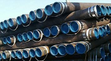 Eastern Steel Manufacturing Co.,Ltd not only improve product production and sales services, but also provide additional value-added services. As long as you need, we can complete your specific needs together.
