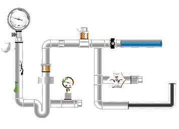
Double-pipe heat exchanger

The double-pipe heat exchanger is currently the most widely used tubular heat exchanger in petrochemical production. It mainly consists of a shell (including inner shell and outer shell), U-shaped elbow tube, stuffing box, etc. The required pipes can be made of ordinary carbon steel, cast iron, copper, titanium, ceramic glass, etc. The tube is usually fixed to a bracket. Two different media can flow in opposite directions (or in the same direction) in the tube to achieve heat exchange.
The double-pipe heat exchanger is made of two standard tubes of different sizes connected to form a concentric casing. During reverse heat exchange, the hot fluid enters from the upper part, while the cold fluid enters from the lower part, and the heat passes through the inner tube wall. Transfer of one fluid to another. The distance that the hot fluid flows from the entry end to the outlet end is called the tube pass; the fluid enters through the nozzle of the shell, is introduced from one end of the shell to flows out from the other end, and the heat exchanger that transfers heat in this way is called Shell side jacketed heat exchanger. Since double-pipe heat exchangers are widely used in petrochemical, refrigeration and other industrial sectors, the original single heat transfer method and heat transfer efficiency can no longer meet actual work and production. At present, domestic and foreign researchers are focusing on shell-tube heat exchangers. Many improvement plans have been proposed to extend the service life of the jacketed heat exchanger and enhance its efficiency.
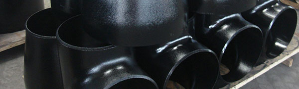
A heat exchanger with an inner tube in a concentric sleeve as the heat transfer element. Two tubes of different diameters are put together to form a concentric casing. Each section of casing is called a "pass". The inner tube (heat transfer tube) of the course is a U-shaped elbow tube, while the outer tube is connected in a row with short tubes. Fixed on the bracket (Figure 1a). Heat is transferred from one fluid to another through the inner tube wall. Generally, hot fluid (A fluid) is introduced from the upper part, while cold fluid (B fluid) is introduced from the lower part. The two ends of the outer tube in the casing are connected to the inner tube by welding or flanges. The inner tube and the U-shaped elbow tube are often connected by flanges, which facilitates cleaning, addition and removal of heat transfer tubes. The effective length of each heat transfer tube is 4 to 7 meters. The heat transfer area of this heat exchanger pipe is up to 18 square meters, so it is suitable for small-capacity heat exchange. When the temperature difference between the inner and outer tube walls is large, a U-shaped expansion joint can be installed on the outer tube (Figure 1b) or a stuffing box sliding seal can be used between the inner and outer tubes (Figure 1c) to reduce the temperature difference stress. Pipes can be made of steel, cast iron, copper, titanium, ceramics, glass, etc. If the materials are properly selected, they can be used for heat exchange in corrosive media.

Classification
1. Fixed tube plate heat exchanger
The structure of this type of heat exchanger is relatively simple, compact, and cheap, but the outside of the tube cannot be cleaned mechanically. The tube bundles of this type of heat exchanger are connected to the tube sheets, which are welded to both ends of the shell and connected to a top cover. The top cover and the shell are equipped with fluid inlet and outlet pipes. A series of baffles are usually installed outside the tubes perpendicular to the tube bundle. At the same time, the connection between the tube and the tube sheet and the shell are rigid, and there are two fluids with different temperatures inside and outside the tube. Therefore, when the temperature difference between the tube wall and the shell wall is large, due to the different thermal expansion of the two, a large temperature difference stress is generated, which may cause the tube to twist or loosen from the tube plate, or even damage the heat exchanger. In order to overcome the temperature difference stress, a temperature difference compensation device must be installed. Generally, when the temperature difference between the tube wall and the shell wall is more than 50°C, for safety reasons, the heat exchanger should have a temperature difference compensation device. However, the compensation device (expansion joint) can only be used when the temperature difference between the shell wall and the pipe wall is lower than 60 to 70°C and the shell side fluid pressure is not high. Generally, when the shell side pressure exceeds 0.6MPa, the compensation ring is too thick, difficult to expand and contract, and loses the temperature difference compensation function, so other structures should be considered.
2. Floating head heat exchanger
One tube plate of the heat exchanger is connected to the shell with a flange, and the other tube plate is not connected to the shell so that the tubes can expand and contract freely when heated or cooled. However, a top cover is connected to this tube plate, which is called " "Floating head", so this heat exchanger is called a floating head heat exchanger. Its advantages are: the tube bundle can be pulled out for cleaning; the expansion of the tube bundle is not constrained by the shell, so when the temperature difference between the two heat exchanger media is large, temperature difference stress will not be generated due to the difference in thermal expansion between the tube bundle and the shell. . Its disadvantages are complex structure and high cost.
3. Packing function heat exchanger
One end of the tube bundle of this type of heat exchanger can expand freely, the structure is simpler than the floating head type, and the cost is lower than the floating head type. However, there is a possibility of leakage of the medium in the shell side, and volatile, flammable, explosive and toxic media should not be handled in the shell side.
4. U-shaped tube heat exchanger
U-shaped tube heat exchanger, each tube is bent into a U shape, and both ends are fixed on the same tube plate. Each tube can be freely expanded and contracted to solve the thermal compensation problem. The tube passes are at least two, the tube bundle can be extracted for cleaning, and the tubes can expand freely. The disadvantages are that it is difficult to clean the inner wall of the tube, difficult to replace the tube, and there are few tubes arranged on the tube plate. The advantages are simple structure, light weight, and suitable for high temperature and high pressure conditions.


 Eastern Steel Manufacturing Co.,Ltd not only improve product production and sales services, but also provide additional value-added services. As long as you need, we can complete your specific needs together.