Pipe joints are indispensable in hydraulic systems, because pipe joints are detachable connections between oil pipes, oil pipes, and hydraulic components. It should meet the requirements of firm connection, reliable sealing, small liquid resistance, compact structure, and easy disassembly and assembly.
There are many forms of pipe joints. According to the direction of the joint, there are straight-through, right-angle, tee, four-way, hinged and other forms; according to the connection method with the oil pipe, there are pipe end expansion type, ferrule type, welding type, and crimp type. Formula etc. Conical threads and ordinary fine threads are commonly used to connect pipe joints to the machine body. When connecting with conical threads, leak-proof packing should be added; when connecting with ordinary fine-thread threads, a combined sealing gasket (a combination of cooked aluminum alloy and oil-resistant rubber) should be used, and a small plane should be machined on the connected piece.
1. Pipe end expansion pipe joint

Flared pipe joint
The working principle of the pipe-end flared pipe joint is shown in Figure 2-1. It is suitable for the connection between copper pipes and thin-walled steel pipes. The nozzle 2 is first expanded into a bell mouth (about 74°~90°), and then the guide sleeve 4 and the nozzle 2 are pressed together with the nozzle 2 on the joint body l using the joint nut 3 to form a seal. The tightening force during assembly is converted into axial pressing force through the joint nut 3, and is transmitted to the nozzle part of the nozzle through the guide sleeve 4, so that the contact specific pressure is obtained between the expanded cone surface and the sealing cone surface of the joint body 1. While playing a rigid sealing role, it also plays a connecting role and withstands the axial component force between the joint body and the nozzle produced by the fluid pressure in the pipe. The maximum pressure of this kind of pipe joint is generally less than 16MPa.
2. Card sleeve military pipe joint

Card sleeve type pipe joint
As shown in Figure 2-2, the basic structure of the ferrule type pipe joint consists of three basic parts: the joint body 1, the ferrule 4 and the nut 3. The ferrule is a metal ring with a sharp edge at the inner end. During assembly, the edge cuts into the connected oil pipe to connect and seal.
During assembly, first put the nut 3 and the ferrule 4 on the nozzle 2, then insert the oil pipe into the inner hole of the joint body 1 (close to it), install the ferrule in the gap between the taper hole in the joint body and the oil pipe, and then put the nut 3. Tighten it on the joint body 1 until the 86° cone surface of the 90° ferrule end of the nut fully contacts. Before tightening the nut with a wrench, be sure to make the end face of the connected oil pipe in contact with the thrust surface of the joint body, and then tighten the nut while turning the oil pipe by hand. If the oil pipe cannot rotate, it means that the clamp is between the nut push and the joint cone surface. The oil pipe has begun to get stuck under the squeeze. Continue to tighten the nut 1-4/3 turns so that the cutting edge of the ferrule cuts into the oil pipe to form a seal between the ferrule and the oil pipe. The outer surface of the front end of the ferrule is conical with the body of the joint. The spherical contact seal formed between the surfaces is another sealing surface.
The outer diameter of the oil pipe used in the ferrule type pipe joint generally does not exceed 42mm, and the operating pressure can reach 40MPa. It works reliably and is easy to disassemble and assemble. However, the manufacturing process of the ferrule is relatively high.
3. Welded pipe joints

Welded pipe joint
As shown in Figure 2-3, a welded pipe joint is a type in which one end of the pipe is welded to the pipe 2 on the pipe joint, and then connected to other pipe components through the nut 3, the joint body 1, etc. on the pipe joint. Pipe joints. The O-ring 4 shown in Figure 74 can be used to seal the joint body 1 and the nozzle 2. In addition, the spherical compression method or the method of adding a metal sealing gasket can also be used for sealing. The pipe joint can also be pressed with a spherical surface as shown in Figure 2-4(a), or a metal sealing ring 4 can be added, and sealed using the method shown in Figure 2-4(b). The latter two sealing methods have low pressure-bearing capacity, and the processing of spherical seal joints is difficult. The connection between the joint body and the component can use the conical thread shown in Figure 5, or the fine-thread cylindrical thread (shown in Figure 4), and a combined sealing gasket 5 can be added to prevent leakage.
The welded steel pipe joint has a simple structure, is easy to manufacture, can withstand high pressure (32MPa) and has good sealing performance. The disadvantage is that the welding quality requirements for steel pipes and pipes are relatively high.
4. hose connector

Spherical compression and metal sealing ring welded pipe joints
Hose joints are generally used in conjunction with steel wire braided high-pressure rubber hoses. They are divided into two types: detachable and withholding. Figure 2-5 shows a detachable hose connector. It mainly consists of a joint nut 1, a joint body 2, a jacket 3 and a hose 4. The hose is sandwiched between the two. After tightening, the connecting part of the hose is compressed to achieve the function of connection and sealing. The crimp type hose connector is shown in Figure 2-6. It consists of a joint nut 1, a joint core 2, a joint sleeve 3 and a hose 4. Before assembly, peel off a layer of outer glue on the hose, then put the joint sleeve on the hose with the outer glue removed, insert the joint core, and then put the joint sleeve on the press bed and use the die to squeeze and shrink, so that the inner cone of the joint sleeve The annular teeth on the surface are embedded in the steel wire layer to achieve a firm connection, and also compress the outer conical surface of the joint core and the inner rubber layer of the hose to achieve the purpose of sealing.
Note that the specifications of hose joints are based on the inner diameter of the hose, and the specifications of metal pipe joints are based on the outer diameter of the metal pipe.
5. Quick Connector

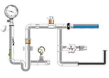
quick connector
A quick connector is a type of oil pipe joint that does not require any tools and can be quickly connected or disconnected. It is suitable for hydraulic pipelines that need to be frequently disassembled. Figure 2-7 shows the structural diagram of the quick connector. The position of each part in the picture is the position when the oil circuit is connected. It has two joint bodies 3 and 9, and both ends of the joint body are connected to pipes respectively. The outer sleeve 8 presses the 3 or 8 steel balls 7 on the joint body 3 into the V-shaped groove on the joint body 9 to connect the two joint bodies. The poppet valve cores 2 and 5 are squeezed together and pushed open to connect the oil circuit. When it is necessary to disconnect the oil circuit, the outer sleeve 8 can be pushed to the left with force and the joint body 9 is pulled out at the same time. At this time, the spring 4 makes the outer sleeve 8 return to its position. Poppet valve cores 2 and 5 extend outward under the action of springs 1 and 6 respectively, and press against the valve seats of joint bodies 3 and 9 to close the oil circuit and seal the oil in the pipes on both sides to prevent it from flowing out.
6. Flange pipe joint
The flange type pipe joint is to weld steel pipe 1 to flange 2 and then connect it with screws. The two flanges are sealed with an O-ring seal, as shown in Figure 2-8. This type of pipe joint has a solid structure, reliable operation, and good vibration resistance; but its size is large and it is suitable for high-pressure and large-flow pipelines.


 Eastern Steel Manufacturing Co.,Ltd not only improve product production and sales services, but also provide additional value-added services. As long as you need, we can complete your specific needs together.