Effect of cooling rate on band structure of seamless carbon steel pipe
The banded structure in steel refers to the structure formed along the rolling direction of the steel. The bands mainly composed of proeutectoid ferrite and the bands mainly composed of pearlite, bainite and martensite are stacked on each other. When the banding structure is severe, the mechanical properties of the steel pipe show obvious anisotropy, which causes the steel pipe's transverse section shrinkage to be greatly reduced, the longitudinal impact energy and the transverse impact energy are greatly different, and the plasticity or toughness of the steel pipe cannot meet the requirements of the technical standards. , some users of seamless steel pipes for boilers clearly require that the level of the banded structure in the steel pipe shall not be greater than level 3.

Improving the segregation of C, Mn and other elements in steel is the fundamental way to eliminate or reduce the banded structure. During the steel rolling process, optimizing the rolling ratio, final rolling temperature and cooling rate after rolling can improve component segregation, refine grains, and reduce banded structures. The faster the cooling rate after rolling, the lighter the banding. Among them, the rolling compression ratio and cooling speed have a relatively obvious impact on the bandwidth of the strip structure. The bandwidth of cooling in air is significantly narrower than the bandwidth of slow cooling; the strip spacing becomes smaller with the increase of the total reduction rate during rolling. In addition to eliminating or reducing the band structure by controlling the rolling process parameters, the structure can also be improved through heat treatment. The optimized system of comprehensive cross-heading forging and high-temperature solution heat treatment of 1 050 9Cx2 h + 820 Cx1 h is adopted to greatly improve the band segregation of the material and ultimately eliminate the band structure. Research shows that the grade of the band structure of the isothermal annealed specimen is lower than that of the ordinary annealed specimen. High-temperature diffusion annealing + normalizing heat treatment can eliminate the band-like structure in 22GrMoH gear steel. Using 1250~1300C dispersed annealing and holding for about 5 hours can eliminate dendrite segregation and thus eliminate the band structure. During the cooling process of normalizing heat treatment, as long as the cooling rate is strictly controlled in the austenite and ferrite two-phase regions, obvious banding can be avoided.
shape organization. During the cooling process of steel after heat treatment, as the cooling rate increases, the actual transformation temperature of ferrite phase transformation gradually decreases, and a further theoretical study was conducted on the mechanism of band-like structure formation.
When producing carbon seamless steel pipes for boilers such as 20G, SA106B, SA106C, etc., due to the dendrite segregation of Mn in the continuous casting billet, band-like structures are often found, reaching levels 4 to 5 in severe cases. Observe the metal structure of the entire wall thickness of the steel pipe. Phase structure found that generally the banding structure on the outer surface of the steel pipe is lighter, the banding structure is obvious in the middle of the wall thickness, and the banding structure on the inner surface is serious. At present, there have been in-depth studies on the influencing factors and process control of banded structures in steel plate production, but there are few reports on solutions to banded structures in steel pipe production. This article mainly studies the effects of different cooling rates on the banded structure of SA106C carbon-manganese seamless steel pipe after normalizing. By observing and analyzing the microstructure, it provides a basis for reducing or eliminating the banded structure production process.
|
Table 1 Chemical composition (mass fraction) of SA106C test steel pipe %
|
|
C
|
Si
|
Mn
|
P
|
S
|
Cu
|
Ni
|
Cr
|
Mo
|
V
|
|
0.20
|
0.28
|
1.18
|
0.015
|
0.006
|
0.04
|
0.02
|
0.05
|
0.01
|
0.003
|
1.2 Test methods
First, the original structure of the SA106C seamless steel pipe was observed, and then the test steel pipe was normalized. The normalizing temperature
(910+5)℃, holding time 30 minutes. In order to obtain the effects of different cooling rates on the band structure, the cooling method of immersing the end of the steel pipe in water was used. The steel pipe formed a gradient from fast to slow from bottom to top. Cooling speed, the cooling method after normalizing is to stand in water and the water depth is 20 mm. After cooling to room temperature, cut 5 metallographic samples along the direction of the tube body, numbered 1 to 5, and observe the structures respectively.
2.Test results
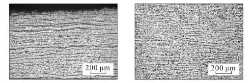
The original structure morphology of SA106C seamless steel pipe is shown in Figure 2. The metallographic structure corresponding to different cooling rates (No. 1~5) is shown in Figure 3. The observation position of the No. 1 metallographic sample is from the bottom of the steel pipe to 3cm away from the bottom of the steel pipe, the observation position of the No. 2 metallographic sample is 3 to 6 cm from the bottom of the steel pipe, the observation position of the No. 3 metallographic sample is 6 to 9 cm from the bottom of the steel pipe, and the observation position of the No. 4 metallographic sample is 3 cm from the bottom of the steel pipe. The observation position is 9~12em from the bottom of the steel pipe, and the observation position of No. 5 metallographic sample is 12~15 cm from the bottom of the steel pipe.
The banded structure grade is rated according to GB/T 13299-1991 "Method for Evaluation of Microstructure of Steel". It can be seen from Figure 2: SA106C seamless steel pipe has banded structure from the inner surface to the middle, and the banded structure grade is from 5 The grade gradually decreases toward grade 2, with the most serious band-like tissue near the inner surface, and gradually decreases in the middle of the wall thickness, while there is no band-like tissue near the outer surface.
As can be seen from Figure 3, the microstructure of the test steel is composed of ferrite and pearlite. The morphology of the structure is determined by the cooling rate. From the bottom of the sample upward, the cooling rate goes from fast to slow, with a slower cooling rate. When the temperature increases, ferrite + pearlite distributed in strips is obtained. As the cooling rate increases, the grains gradually become refined and the striped structure gradually disappears, replaced by evenly distributed ferrite and pearlite. Pearlite The number of ferrite in the strips increases, causing the pearlite to become discontinuous. As the cooling rate further increases, the pearlite strips first become thinner, and the number of strips decreases. When the cooling rate increases to a certain extent, pearlite appears. body structure. The structural changes in the middle part of the wall thickness of the steel pipe follow the same pattern as the inner surface, while the original structure in the middle part of the wall thickness is smaller than that on the inner surface.
Generally speaking, the banding structure is relatively mild, so the banding structure level in the middle part of the wall thickness is reduced to below grade 2. The change trend of banded tissue level is shown in Figure 4. The range of metallographic structure type and banded tissue level that meets the standards and user requirements is 3~9 cm from the bottom. The hardness distribution of SA106C steel pipe near the inner surface is shown in Figure 5.
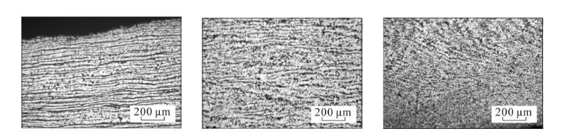
(a) Close to the inner surface (b) Middle of wall thickness (c) Close to the outer surface.
Figure 2 Original microstructure morphology of SA106C seamless steel pipe
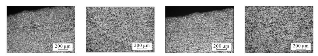
(a) The bottom of the steel pipe is close to the inner surface (b) The middle of the wall thickness at the bottom of the steel pipe (c) 2 cm from the bottom of the steel pipe and close to the inner surface (d) The middle of the wall thickness 2 cm from the bottom of the steel pipe
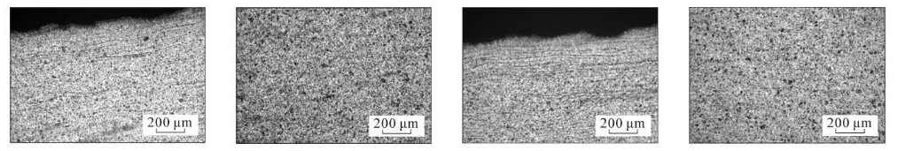
(e) 3 cm from the bottom of the steel pipe, close to the inner surface (f) 3 cm from the bottom of the steel pipe, in the middle of the wall thickness (g) 4 cm from the bottom of the steel pipe, close to the inner surface (h) 4 cm from the bottom of the steel pipe, in the middle of the wall thickness
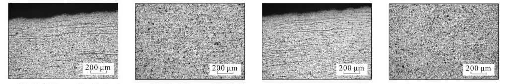
(i) 5 cm from the bottom of the steel pipe, close to the inner surface (j) 5 cm from the bottom of the steel pipe, in the middle of the wall thickness (k) 6 cm from the bottom of the steel pipe, close to the inner surface (l) 6 cm from the bottom of the steel pipe, in the middle of the wall thickness
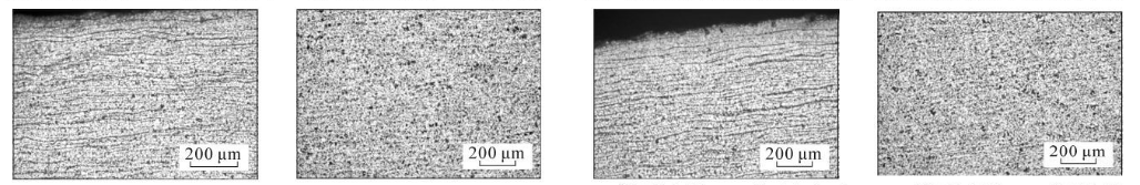
(m) 7 cm from the bottom of the steel pipe, close to the inner surface (n) 7 cm from the bottom of the steel pipe, the middle of the wall thickness (o) 8 cm from the bottom of the steel pipe, close to the inner surface (p) 8 cm from the bottom of the steel pipe, the middle of the wall thickness
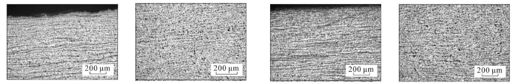
(q) 9 cm from the bottom of the steel pipe, close to the inner surface (r) 9 cm from the bottom of the steel pipe, the middle of the wall thickness (s) 10 cm from the bottom of the steel pipe, close to the inner surface (t) 10 cm from the bottom of the steel pipe, the middle of the wall thickness
(u) 12 cm from the bottom of the steel pipe, close to the inner surface (v) 12 cm from the bottom of the steel pipe, in the middle of the wall thickness
Figure 3 Metallographic structures corresponding to different cooling rates
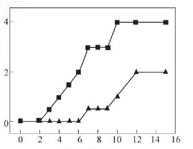
X: Distance from bottom/cm
Y: Band organization level
Upper (inner surface) Lower (middle)
Figure 4 Trend of band organization level changes
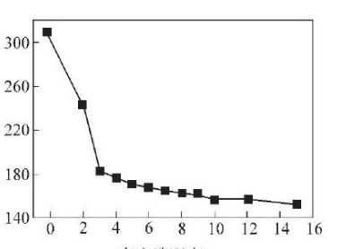
X: Distance from bottom/cm
Y: hardness HV
Figure 5 Hardness change trend of SA106C steel pipe near the inner surface
3. Band tissue analysis
3.1 Causes of formation of band tissue
The formation of the banded structure is caused by the dendrite segregation formed during the solidification process of the continuous casting billet, which is believed to be mainly affected by Mn segregation. In the solidified dendrite structure, the Mn content between dendrites is relatively high, and the Mn content at the branches is relatively low. When the continuous casting billet is heated, C as an interstitial solid solution atom is easily diffused and distributed inside the austenite, while the substitutional solid solution atoms Mn, Si, Cu, Cr, etc. are more difficult to homogenize and are still in a state of dendrite segregation. During the hot rolling process, the dendrite structure is twisted, broken, and elongated due to deformation. Mn segregation remains or is not completely eliminated after rolling, forming poor Mn bands and rich Mn bands in the austenite before cooling phase transformation. Mn is an austenite stabilizing element, which reduces A. Temperature, due to the banded segregation of Mn elements will lead to differences in As temperature in different parts, resulting in anisochrony of proeutectoid ferrite2. The band-shaped area with high Mn content has low A3 and is less likely to produce ferrite, while the area with relatively low Mn content precipitates the ferrite structure first. Therefore, during cooling after rolling, the Mn-poor band in austenite will undergo ferrite transformation first to form a ferrite band, and the supersaturated precipitated C atoms will diffuse to the Mn-rich band, further suppressing the ferrite in the Mn-rich band. The precipitation of Mn-rich austenite eventually transforms into pearlite zone. Therefore, the prerequisite for the generation of banded structure is the difference in A3 temperature caused by the uneven chemical composition in each banded area. The result of the banded distribution of components results in the ferrite + pearlite banded structure obtained after phase transformation.
3.2 Effect of cooling rate on strip structure of test steel
Accelerating the cooling rate will lower the transformation temperature of the ferrite, reduce the difference in phase transition starting temperature of the component segregation zone, reduce the anisochrony of the ferrite, and help reduce the band structure. Accelerating cooling leads to a decrease in Aa temperature, resulting in a greater degree of supercooling, which increases the nucleation rate of ferrite. At the same time, the lower phase transformation temperature reduces the growth rate of ferrite, which affects the diffusion of C in steel. It has an inhibitory effect, hindering the isotropic growth of ferrite grains, and the formed ferrite is no longer equiaxed. This change in ferrite morphology "cuts" the austenite grains, making pearlite It cannot become a continuous band, thereby weakening the band organization. However, if the cooling rate is too high to form a Widmanstatten or bainite structure, it will be detrimental to the overall performance of the steel pipe.
In order to determine the impact of cooling rate on the banded structure, obtain the optimal cooling rate range, and ensure that production can not only reduce the banded structure, but also ensure that the steel pipe structure avoids unqualified structures such as Widmanstatten or bainite, and draws the SA106C steel pipe. The CCT curve is shown in Figure 6. According to the corresponding relationship between hardness value and cooling rate (Table 2), a regression analysis is performed on the cooling rate and steel pipe hardness to find out the relationship between the two. The regression analysis results are shown in Figure 7.
The regression equation between Vickers hardness and cooling rate is:
y=0.002 5x2-0.731 5x+54.214 (1)
Y—cooling rate, ℃/s;
X—Vickers hardness, HV.
The Vickers hardness 3~9 cm from the bottom is 163~182 HV, and the cooling rate calculated with formula (1) is 1.40~3.89 C/s, which
It shows that by controlling the cooling speed at 1.40~3.89℃/s, the band tissue level can be controlled at level 0~3, which meets the standards and user requirements.
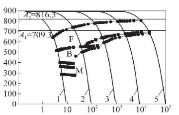
X: time/s
Y: Temperature/℃
1-435HV 2-232HV 3-168HV 4-151HV 5-143HV
Figure 6 CCT curve of SA106C steel
|
Table 2 Corresponding values of hardness and cooling rate in CCT curve
|
|
Vickers hardness HV
|
151
|
160
|
175
|
192
|
200
|
|
Cooling rate
(℃*S-1)
|
0.10
|
0.82
|
2.05
|
4.30
|
7.60
|
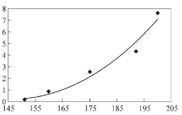
X: Vickers hardness, HV
Y: cooling rate, ℃*S-1
Figure 7 Regression analysis results of hardness and cooling rate
4. Production application
The company adopts the steel pipe rotating internal spray and external spray cooling method to quickly cool the normalized 20G, SA106B, SA106C and other carbon high-pressure boiler tubes. The specification span is 76.2~720 mmx10~120 mm. Corresponding pipes are designed for different specifications. With the cooling speed control scheme, the strip structure level of the steel pipe is controlled below level 3. It supplies more than 10,000 tons in batches to domestic boiler manufacturers every year and has received good feedback from users.
5. Conclusion
(1) The microsegregation of Mn element is the main reason for the banded structure. The banded structure is the most serious near the inner surface of SA106C steel pipe, and gradually reduces in the middle of the thick wall. There is no banded structure near the outer surface.
(2) Accelerate the cooling rate after normalizing to lower the ferrite transformation temperature, reduce the difference in phase transformation starting temperature in the component segregation zone, reduce the anisochrony of ferrite production, and increase the ferrite The nucleation rate reduces the growth rate of ferrite, hinders the isotropic growth of ferrite grains, and the formed ferrite is no longer equiaxed. This change in ferrite morphology "cuts" "Open" austenite grains prevent the pearlite from becoming a continuous band, thereby weakening the band structure.
(3) When the cooling rate of SA 106C steel pipe is controlled at 1.40~3.89℃/s, the band structure is grade 0~3, which ensures that the production can not only reduce the band structure, but also avoid the occurrence of unqualified structures such as Widmanstatten or bainite.


 Eastern Steel Manufacturing Co.,Ltd not only improve product production and sales services, but also provide additional value-added services. As long as you need, we can complete your specific needs together.