Factors affecting the compressive strength of OCTG casing
In practical applications, natural environmental factors cannot be artificially changed. The life of an oil well mainly depends on the quality of the oil casing. Since there are many factors that affect the crushing strength of casing, it is very difficult to study these influencing factors using physical tests. The finite element method has unique advantages. The finite element method can conveniently and accurately analyze the crushing strength of casing under different conditions, which is incomparable with experimental methods and theoretical analysis methods. Research on various factors that affect the quality of oil and casing has never stopped, especially the ovality and unevenness of wall thickness during the manufacturing process, which have the most significant impact on the collapse strength of oil and casing, which can directly lead to the collapse of oil and casing. The carrying capacity is significantly reduced.

Since there are currently few studies on the changes in the collapse strength of oil casing due to ovality and wall thickness unevenness under uniform loads, this paper selects casing with a medium size of 101.6 mmx7.8 mm. Under the condition of uneven ovality and wall thickness, a uniform load is applied to the pipe body. A comparative analysis and study is conducted on the relationship between the collapse strength and the ovality and wall thickness of the oil casing under uniform load are analyzed and summarized. The changing pattern between unevenness and collapse strength.
1. Establishment of finite element model of casing collapse
1.1Basic assumptions
The fixed casing downhole is taken as a separate research object. Since the ratio of the diameter of the casing to its length is very small, when establishing the finite element model, the casing can be treated as an infinitely long tube and simplified into a plane strain problem. The following basic assumptions are made for the mechanical model and extrusion load distribution form of the casing:
① Before deformation, the casing is an ideal circle with uniform wall thickness;
②After deformation, the casing is symmetrical relative to the center of the pipe body;
③A uniform extrusion load acts on the casing.
1.2 Establishment of geometric model
The ovality and wall thickness errors of the casing have a significant impact on its collapse resistance, so the establishment of the geometric model needs to take these two into account.
the influence of In order to study the relationship between ovality and wall thickness unevenness and the external extrusion resistance of casing, it is necessary to analyze the ovality and wall thickness unevenness as variables respectively. When studying the effect of ovality on casing anti-extrusion, it is assumed that the casing wall thickness is uniform everywhere, and ovality exists in both the inner hole and the pipe wall. The expression of ovality is shown in Figure 1. When studying the effect of uneven wall thickness on the anti-extrusion resistance of casing, it is assumed that the outer wall of the casing is ideally circular and the inner hole is eccentric, resulting in uneven wall thickness. The non-round inner hole is not considered here, only the non-roundness of the inner hole is considered. Uneven wall thickness caused by eccentricity, uneven wall thickness
The expression form of degree is shown in Figure 2.
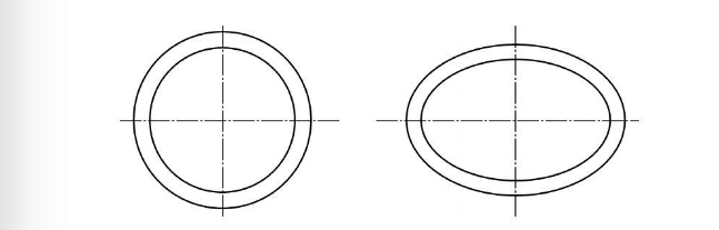
(a) Ideal circular tube (b) There is ovality
Figure 1 Schematic representation of cross-sectional shape of casing with ellipticity
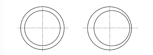
(a) Ideal circular tube (b) Uneven wall thickness exists
Figure 2 Schematic representation of the cross-sectional shape of a casing with uneven wall thickness
Select the oil casing with medium size of 101.6 mmx7.8mm for finite element analysis. Taking into account the geometric characteristics of the structural boundary, the symmetry of the structure and the force, a 1/2 ring is taken for study, and the finite element model is as shown in Figure 3. shown. The model is established by changing the ellipticity and adjusting the eccentricity to correct the accuracy of the model. For the structural type of casing, the structure is relatively simple, so it is suitable to use quadrilateral four-node elements. In order to facilitate comparison and verification with the test results, the material properties of the model are based on the test values of the sample. The elastic modulus E is 210 GPa, the Poisson's ratio is 0.3, and the yield strength is 667 MPa. The influence of the material tensile strength is ignored, and only the The influence of yield strength is because the collapse failure of casing is different from the tensile failure. When calculating the collapse failure load of casing through the finite element method, the yield strength of the material should also be used as the basis, rather than the tensile strength. . A uniform load is applied to the outside of the casing finite element model shown in Figure 3, and axial movement constraints are applied to the nodes on the symmetry plane at the bottom of the model to eliminate the rigid body displacement of the model. The calculation uses nonlinear finite element analysis of elastic-plastic large deformation.
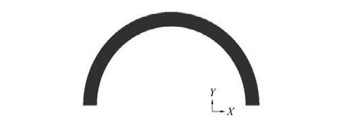
Figure 3 1/2 ring finite element model of Ф101.6 mmx7.8 mm specification casing
2. Experimental verification
It is impossible to process the actual casing into an ideal round pipe, and the wall thickness of the casing cannot be completely uniform, and there are always certain processing defects. This geometric defect exists in the outer diameter and wall thickness deviation on the same cross-section, which can be expressed by outer diameter ovality and wall thickness unevenness respectively. In order to verify the accuracy of the finite element model, the finite element calculation results were compared with the experimental measurement data through the casing collapse test.
2.1 Test content
The casing collapse test needs to test the collapse pressure and the resulting strain. The strain test system consists of two parts: a collapse testing machine and a data acquisition and processing system. During the test, first paste the strain gauge on the outer wall of the casing and provide insulation protection for the strain gauge. Lead the test wire through the sealing plug and place it in the crush testing machine. Connect the wire to the data acquisition system through the junction box and collect the test. During the process, the strain changes as the pressure increases, and the data is transmitted to the computer. A petroleum casing with a size of 101.6 mmx7.8 mm was selected, and a strain gauge was attached to the outer wall of the casing to measure the deformation and final failure load of the casing during the collapse process. The test procedures and steps are as follows:
(1) Material performance test: According to the requirements of CB 6397-1986 "Metal Tensile Test Specimens", take tensile specimens from the casing body under test. In accordance with the provisions of CB/T 228.1--2010 "Tensile Test of Metal Materials Part 1: Room Temperature Test Method", conduct the tensile property test of the material to obtain the yield strength of the casing;
(2) Geometric dimension measurement: Select a section and use an ultrasonic thickness gauge to measure the thickness of the casing, and use a vernier caliper to measure the outer diameter of each section of the casing;
(3) Residual stress detection;
(4) Paste the strain gauge, as shown in Figures 4~5;
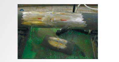
Figure 4 Strain gauge attachment
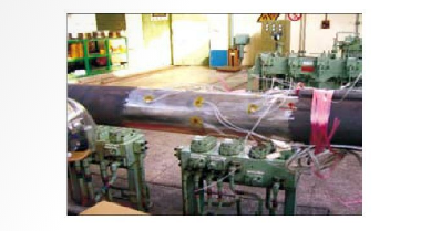
Figure 5 Strain gauge wire welding
(5)Seal coating;
(6) Pressure test;
(7) Measure the circumferential strain of the outer wall of the casing and study the changes in the outer wall of the casing.
Changes in hoop strain as pressure increases.
2.2 Verification of test results
A 101.6mmx7.8mm N80 steel grade casing is selected as an example for analysis. When establishing the finite element model, four 101.6 mmx7.8 mm casings were selected for the test and numbered 1, 2, 3, and 4 respectively. During the test, the geometric parameters (outer diameter, wall thickness) of four samples were tested respectively, based on the actual measured geometric parameters. According to on-site measurements, the geometric dimensions of the four specimens are shown in Table 1, and the test results of mechanical properties are omitted.
|
Table 1 Geometric dimensions of 4 casings with φ101.6 mmx7.8 mm specification /mm
|
|
Casing number
|
Dmax
|
Dmin
|
tmax
|
tmin
|
|
1
|
102.24
|
101.90
|
8.10
|
7.81
|
|
2
|
102.82
|
101.10
|
8.15
|
7.72
|
|
3
|
102.82
|
101.02
|
8.28
|
7.62
|
|
4
|
102.06
|
101.48
|
8.21
|
7.58
|
As can be seen from Table 1, the diameter-thickness ratio (D/t) of φ101.6 mm and "Announcement of Calculations and Formulas for Line Pipe Performance" standard, which belongs to the plastic collapse mode, that is, the failure of the casing is caused by the structural instability after local plastic deformation. Through simulation calculations, the final collapse pressures P of the four casings were 119.3, 103.1, 100.8, and 108.2 MPao. A collapse testing machine was used to conduct external pressure collapse tests on the above four specimens. During the test, the external extrusion force was gradually increased uniformly from 0 until the casing finally collapsed, and the final collapse strengths P2 of the casing were obtained as 100, 87, 86, and 92 MPa respectively. The errors between the test value and the calculated value of the collapse strength are 193%, 18.5%, 17.2%, and 17.6% respectively, and the errors are all within 20%. It can be seen that the model is in good agreement with the test results, the finite element model is reasonable, and can be used to calculate the crushing strength of oil casing.
3.Calculation results and analysis
3.1 Verification of the influence of ellipticity
Using the above finite element model, under the condition that the material properties are exactly the same, one of the two factors, ovality and wall thickness unevenness, is changed to calculate the collapse strength value of the casing. For ease of explanation, the ovality is represented by e, and the wall thickness unevenness is represented by ε. The allowable range of ovality is 0~5%, and the allowable range of wall thickness unevenness is 0~10%. Using the above modeling method, ignoring the influence of uneven wall thickness and assuming uniform wall thickness, the effect of ovality on the crushing strength of the casing is studied. The obtained casing collapse pressure value is shown in Table 2. When the ovality reaches 5 %, the equivalent total strain of the pipe body is shown in Figure 6. In order to facilitate the observation of the relationship between ovality and casing crushing strength, the curve shown in Figure 7 is drawn based on the data in Table 2.
|
Table 2 Data on the relationship between ovality and external crushing pressure
|
|
e/%
|
0
|
0.1
|
0.2
|
0.4
|
0.6
|
1
|
2
|
5
|
|
Pmax/MPa
|
130.21
|
121.41
|
119.83
|
117.02
|
114.41
|
108.61
|
98.6
|
71.82
|
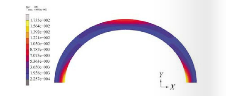
Figure 6 Equivalent total strain cloud diagram of the pipe body when the ellipticity is 5%
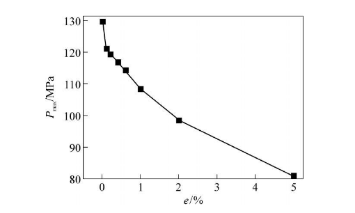
Figure 7: Relationship between casing ovality and external collapse pressure.
Based on the above data and curves, the analysis can be seen:
(1) The ovality of the casing has a prominent impact on the anti-crush performance. As the ovality increases, the anti-crush performance of the casing decreases. For φ101.6 mmx7.8mm (N80 steel grade) casing, within the allowable ovality tolerance range, the load-bearing capacity dropped by 37.94%.
(2) Under different ovality conditions, as the e value increases, the anti-crush performance of the casing decreases to different degrees. In the range of 02%, the bearing capacity decreases more gently, but the bearing capacity It has dropped to about half of the ideal load-bearing state, with a decrease of more than 24.27%.
3.2 Verification of the influence of wall thickness unevenness
Using the above model, ignoring the influence of ovality, model and solve the casing with different wall thickness unevenness. The calculation results are shown in Table 3. When the wall thickness unevenness reaches 10%, the equivalent total strain of the pipe body is As shown in Figure 8, in order to facilitate the observation of the relationship between wall thickness unevenness and casing crushing strength, the relationship curve between wall thickness unevenness and external collapse pressure shown in Figure 9 is drawn based on the data in Table 3.
|
Table 3 Data on the relationship between wall thickness unevenness and external collapse pressure
|
|
ℇ/%
|
0
|
0.5
|
2.5
|
5
|
7.5
|
10
|
|
Pmax/MPa
|
130.21
|
124.20
|
122.81
|
121.60
|
120.65
|
120.00
|
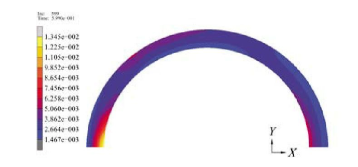
Figure 8 Equivalent total strain cloud diagram of the pipe body when the wall thickness unevenness is 10%
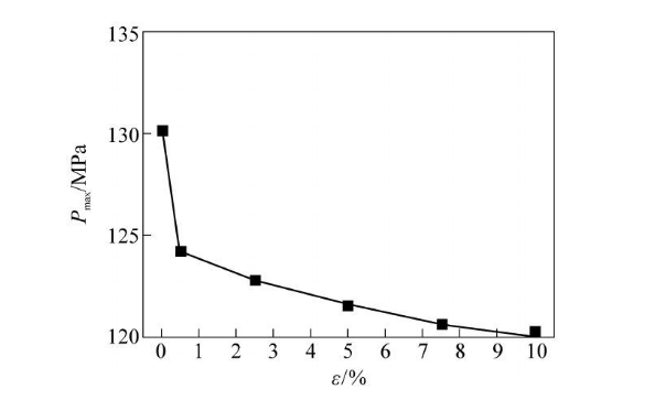
Figure 9 Relationship between wall thickness unevenness and external collapse pressure
According to the above data and curves, it can be seen through analysis:
(1) As the unevenness of casing wall thickness increases, the anti-extrusion performance decreases. For 101.6 mmx7.8 mm (N80 steel grade) casing, within the allowable wall thickness unevenness tolerance range, the load-bearing capacity decreased by 7.84%.
(2) The anti-extrusion performance decreases to different degrees within different ranges of t. When 0<8<0.5%, the anti-extrusion performance of the casing decreases sharply, and the load-bearing capacity decreases by about 4.84% in the entire range; when 0.5%<8<5%, the decrease in load-bearing capacity tends to ease, and the load-bearing external pressure is similar to the unevenness. Linear relationship: for every 0.1% increase in wall thickness unevenness, the bearing capacity decreases by about 0.104 MPa; when 5%<8<10%, the casing bearing capacity decreases more slowly, and the bearing capacity of the casing over the entire interval is the same as the wall thickness unevenness. For an approximately linear relationship, for every 0.1% increase in wall thickness unevenness, the anti-extrusion capability of the casing decreases by approximately 0.032 MPa.
3.3 Result analysis
The collapse strengths of the four samples under the influence of ellipticity e were 117.99, 101.71, 100.91, and 114.8 MPa respectively. The errors from the test value P2 were 0.98%, 1.07%, 0.21%, and 6.11% respectively, and the errors were all within 10 Within %. The collapse strengths under the influence of wall thickness unevenness are 122.25, 121.44, 120.44, and 120.43 MPa respectively. The errors from the test value P are 22.3%, 39.6%, 40.0%, and 30.9%, respectively, and the errors are all within 20%. superior. It can be seen that ovality is the main influencing factor of casing anti-crush strength, and wall thickness unevenness has a relatively small impact on casing anti-crush strength.
4.Conclusion
(1) The load-bearing capacity of an ideal circular casing is higher than that of an elliptical casing. As the ovality increases, the load-bearing capacity of the casing decreases, and there is a linear relationship between them; the anti-collapse capacity of an ideal round pipe is higher than that of an elliptical casing. The actual casing with uneven wall thickness is higher. As the uneven wall thickness increases, the collapse resistance of the casing decreases accordingly, and there is a linear relationship between them. As the ovality and wall thickness unevenness increase, the critical collapse pressure of the casing gradually decreases, and the ovality has a greater impact on the crushing strength of the casing, while the wall thickness unevenness has a relatively small impact. .
(2) In specific experimental studies, due to the coexistence of initial ovality and wall thickness unevenness, it becomes very difficult to separately calculate or study the impact of one of the two defect factors on the crushing strength. The finite element law does not have such restrictions, which is its advantage.
Read more: The causes of OCTG casing stuck or What are the grades of OCTG casing?


 Eastern Steel Manufacturing Co.,Ltd not only improve product production and sales services, but also provide additional value-added services. As long as you need, we can complete your specific needs together.