Calculation of Unit Rolling Pressure in Cross Rolling of Seamless Steel pipe
In the hot-rolled seamless steel pipe production process, cross rolling process is the most commonly used rolling process. In addition to the extrusion process, the hot rolling of seamless steel pipes, which transforms solid tube billets into hollow billets, currently adopts various structural forms evolved from the roller cross-rolling piercing machine invented by the Mannesmann brothers. roller piercing machine. In the secondary extension and deformation process of hot rolling of seamless steel pipes, in addition to the longitudinal rolling process, the oblique rolling and extension rolling unit is also a widely used rolling deformation process.
As process design, deformation analysis, and pipe mill equipment structure design, cross rolling rolling force parameters are important process and equipment design parameters. Compared with the longitudinal rolling process, the geometric relationship of the deformation space formed by cross rolling is complex, and it is difficult for the longitudinal rolling process to simplify the actual stress and strain state into a plane stress or axisymmetric stress state for analysis and solution. The three-dimensional space analysis of cross rolling is difficult to deal with mathematically. So far, there has been no theoretically accurate deformation analysis of cross rolling and direct theoretical calculation of cross rolling pressure. In fact, the calculation of cross rolling force still adopts the method of longitudinal rolling. A simplified or approximate calculation of a mathematical formula.
Based on the three-dimensional structure of the cross-rolling space, combined with the characteristics of the cross-rolling deformation, according to the plastic mechanics deformation and its deformation principle, the mathematical analytical relationship is established directly from the cross-rolling deformation space and the stress state of the deformation area, and a new cross-rolling deformation analysis is obtained. The engineering plastic mechanics solution of cross rolling and rolling pressure calculation is used for cross rolling deformation analysis and cross rolling force parameter calculation.
1 Spatial structure and deformation characteristics of skew rolling
During cross rolling, the rolling deformation of the rolled piece is completed in the deformation space (pass) formed by the external deformation tool (roller) and the internal deformation tool (plug or mandrel) and the roll. Plastic flow and forming of the metal. Generally speaking, the guide or guide device (guide plate or guide plate) that constitutes the pass only plays the role of restricting the deformation, so when calculating the rolling pressure of cross rolling, only the relationship between the roll and the internal tool (plug, mandrel) is used. The stresses on surfaces in indirect contact with the space are calculated.
As we all know, the roll shape of the skew rolling mill is a curved surface of rotation composed of a curve that rotates around the roll axis (in engineering applications, generally several straight lines form the roll surface curve. Line), in other words, the section perpendicular to the roll axis is a circular section. The rolls of skew rolling mills have different installation arrangements on different skew rolling mills. The space angle of the rolls is determined by the advancing angle (or feeding angle) and rolling angle (or expanding angle). For any skew rolling mill roll, once the advance angle and rolling angle of the roll and the distance between the roll and the rolling center (to be precise, it is the minimum roll spacing of the two-roll skew mill, the three-roll mill is the smallest inscribed circle diameter formed by 3 rolls), then the rolls are completely fixed in the cross-rolling mill, which is also equivalent to the adjustment of the rolling mill in place in actual rolling. As an internal tool for skew rolling deformation, such as: plug or mandrel perpendicular to the rolling center is a circular section, and the whole is a rotating surface with the rolling center as the axis. When the positions of the rolls and internal tools are determined, the rolling deformation space of the skew rolling mill is completely determined. The composition of cross-rolling deformation pass is shown in Figure 1, which is a three-dimensional deformation pass composed of two-roll skew rolling rolls and guide discs. The cross-rolling deformation zone is shown in Figure 2. In order to facilitate the observation of the inside of the deformation zone, only one roll is used here to represent it. The deformation zone of the other roll is characterized by axisymmetric, and the deformation conditions are exactly the same. In addition, for the three-roll cross rolling, the deformation zone formed by the roll is the same as the mathematical description of the spatial structure analysis of the two-roll.
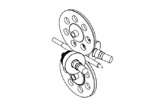
Figure 1 Schematic diagram of cross rolling deformation pass configuration
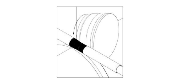
Figure 2 Schematic diagram of cross rolling deformation zone
In the deformation process of skew rolling, the rolled piece advances helically, that is, any material particle or deformed micro-unit in the rolled piece takes the rolling center as the axis and forms a helical line along the rolling direction. It must be emphasized that, determined by the characteristics of the roll shape and the spatial arrangement of the rolls in the skew rolling mill, the cross rolling is a completely non-uniform deformation, and the spatial stress state at any point in the deformation zone is completely different, that is, the principal stress vectors are different. In other words, within any pitch of cross-rolling deformation (cross-rolling deformation zone), the stress state of any two points is completely different (including the deformation history state), so the uneven deformation and asymmetry of cross-rolling are the remarkable characteristics of its deformation .
In view of the particularity of cross-rolling deformation, none of the existing methods has a relatively strict mathematical solution in theory, and basically still adopts a simplified method to calculate the rolling force parameters. The main method is basically to borrow the unit pressure of the longitudinal rolling plate, and then calculate the deformation contact area of the cross rolling deformation zone, and finally obtain the total rolling pressure. Obviously, there is a big difference between longitudinally rolled plate and cross-rolled pipe. In addition, the cross-rolled contact surface is simplified to a two-dimensional plane in three-dimensional space, and the error itself is large.
2 Engineering solution of cross rolling unit rolling pressure
2.1 Deformation characteristic section and coordinates in the cross-rolling deformation zone
As mentioned above, although the deformed material particles (or micro-units) are deformed along the three-dimensional space helix and move plastically in cross-rolling deformation. Inspecting the movement path of the deformed particles, it can be assumed that during the skew rolling deformation process, the deformed material particles move along the vertical section of the same roll axis on the roll surface from the roll biting to the roll throwing, in other words, the deformed material is ignored The slip in the vertical direction between the roll surface and the forward direction (lateral slip Ɛ2=0), it is considered that the metal is on the same roll circular section from the roll bite to the throw. According to this setting, the spatial coordinate system of the selected deformation zone is to use the roll axis (Z axis) as the spatial rectangular coordinate system (XYZ coordinates) in the deformation zone. The roll is broken on the X-Y surface, as shown in Figure 3, the roll section (X-Y surface) is called the cross-rolling deformation characteristic section, which is used as the basic surface for deformation stress analysis. In Figure 3, in the X-Y plane, the cross section of the roll is a circle, and the internal tool (plug or mandrel) is an ellipse. For the convenience of calculation, the internal mandrel section (or plug section, the plug and mandrel The difference is only the variation of the cross-sectional diameter of the round face)
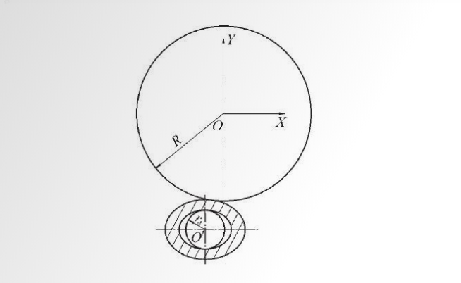
Figure 3 X-Y schematic diagram of the vertical section of the skew rolling roll shaft
The ellipse of can also be simplified and replaced by an inscribed circle (equivalent circle, whose radius is r).
2.2 Geometric relationship of deformation feature section
In any X-Y plane of the cross-rolling deformation zone, the geometric relationship among the rolls, internal deformation tools, and the rolled piece, that is, the geometric relationship within the characteristics of the cross-rolling deformation zone is shown in Figure 4.
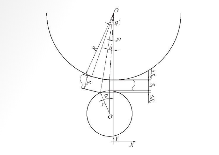
Fig.4 Schematic representation of the geometric relationship within the features of the cross-rolling deformation zone
R - section roll radius
S0-The incoming thickness of the rolled piece on the section (bite thickness)
S1-the exit thickness of the rolled piece at the section (rolled out thickness)
ω-roll X-Y section rolling
The angle formed by the roll axis (0 point) deviating from the mandrel axis (0' point)
In Fig. 4, ω is determined by the spatial arrangement angle (feeding angle, rolling angle) of the rolls in the cross-rolling mill. From Figure 4, the following geometric relations can be established:
Therefore, a and ϕ can be determined by equation (5), and a' can be determined by equation (6):
2.3 Stress state of the cut block of the deformation element in the deformation characteristic section
The section of the deformation unit in the skew rolling deformation zone is shown in Figure 5, and the section should be balanced as shown in Figure 6. The shaded section is any principal stress section in the deformation area, and it can be considered that this section has no shear stress in engineering calculations .
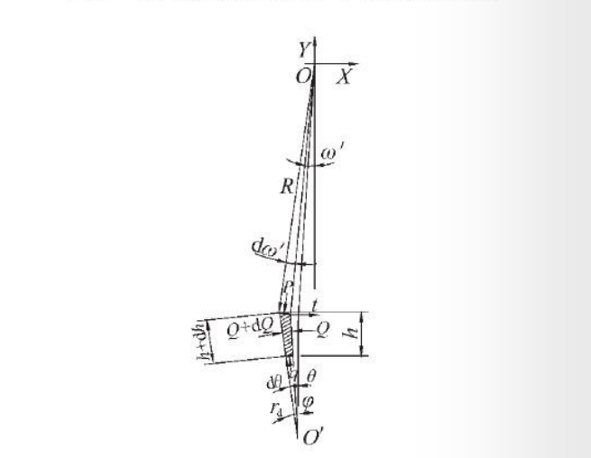
Fig.6 Schematic diagram of stress balance of deformation element
P-contact stress between roll and cutting unit (unit rolling force) Q-cutting unit method
Principal stress q-stress on internal tool t-friction force h-cut height
In Fig. 6, the frictional force t=μP. Since the external tool (roller) has a larger ratio than the internal tool in steel pipe rolling, the backward slippage of the surface during rolling can be ignored.
2.4 Establishment of Differential Equations of Slice Stress in Deformation Elements
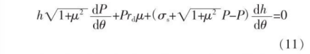
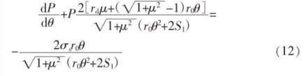
In the deformation zone, when the force ∑Fx=0 in all X-axis directions, the balance relationship of the force in the section (X-Y plane) is formula (7); when the force ∑Fy=0 in all the Y-axis directions, ) force balance relation is formula (8):
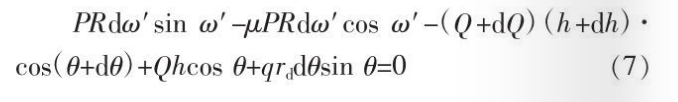
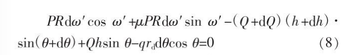
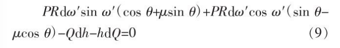
Combining formulas (7)~(8), expanding each item and omitting the secondary high-order trace, we can get:

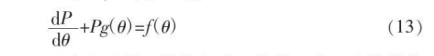
2.5 Solution of differential equation for rolling unit pressure
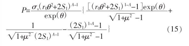
The terms of equation (14) can be integrated. In the integral calculation, the denominator of the integrand appears in the second term of equation (12)

In formula (15)
3 Calculation example of cross rolling unit rolling pressure
Figure 7 shows the roll shape of a cross rolling pipe mill (cross rolling extension machine). The installation and adjustment parameters of rolls in this skew rolling mill are: rolls

Figure 7. Schematic diagram of the roll shape of a cross-rolling pipe mill (cross-rolling extension machine) (rolling angle 10°).
Feeding angle ϕ0 is 8°, rolling angle β0 is 10°, pass throat diameter (minimum roll spacing) 190.42mm; mill incoming material size (capillary specification) Ф215 mmx12.5 mm, rolled out size (barrel tube specification) Ф195 mm, x5.2 mm.
The roll radius R=1 118/2=559 mm at the uniform wall section of the roll, and the calculation steps of the unit rolling force on the section roll at the beginning of the uniform wall section of the roll are as follows:
(1) Calculate the equivalent mandrel radius rd, rd is 183.811 mm;
(2) The wall thickness S1 of the rolled roll in the uniform wall section of the roll is 5.2 mm;
(3) Calculate the bite point of the roll section or the wall thickness S0 of the incoming material on the section, and S0 is the metal rolled out by receiving another roll on the section.
The thickness of the wall rolled out by the half-pitch of the motion is determined by the spatial geometric relationship between the roll shape and the internal tool (mandrel) and the pitch. Once the mill adjustment is confirmed, S0 is uniquely determined, obviously S0≥S1. For the convenience of calculation, take S0=2S1, that is, S0=10.4 mm.
(4) From the formula (5), it can be calculated that the cross-section roll will roll S0 to S1, and the range of the angle corresponding to the equation (15), that is
0≤θ≤ϕ.
The analysis shows that due to the feed angle formed by the roll, the section from the entrance to the exit of the roll changes from a negative value to a positive value. There is always a section where ω is 0. After this section (the direction of the rolled piece exit), ω gradually changes from 0 Incremental (mirror symmetrical with the gradual decrease of the entrance), at the beginning of the uniform wall section (that is, at the minimum roll spacing), ω=0 can be taken as the representative section for calculation.
Substituting S1, R, S0, rd into formula (5), it can be solved that ϕ=13.61°
(5) From the formula (15), it can be calculated that the change of the unit stress of the roll on the rolling section from the rolling bite to the rolling throw on the rolling section can be calculated. It can be seen from the analysis that the unit rolling force at any point on the contact surface of the rolls in the deformation zone of cross rolling is obviously different, which is also the characteristic of uneven deformation of cross rolling. By analyzing the deformation in the whole cross-rolling area, the specific deformation geometric characteristics of the roll shape of any cross-rolling mill and the cross-rolling deformation space structure (pass configuration parameters) formed by the rolls can be directly obtained to obtain the Specific quantitative calculation results of the restraining force or the contact stress between the material and the roll surface. In other words, except for the two physical indicators of the deformation stress of the deformed material and the friction state of the roll surface, the deformation stress of cross rolling is completely related to the deformation zone.
It is related to any element, specifically the diameter of the roll, the size of the internal tool, the roll shape curve, the installation angle of the roll and the adjustment parameters.
4 Epilogue
Through deformation analysis and selection of specific reference coordinates, the theoretical analysis of the complete mathematical relationship of cross rolling deformation rolling unit pressure can be obtained, that is, formula (15), which can be used in the design and calculation of cross rolling force energy parameters and cross rolling deformation stress analysis. It also provides an analytical research method for the complex deformation analysis of cross rolling.
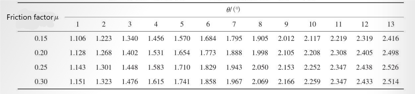
Table 1 P/σs values from the section at the bite point (ϕ=13.61°) to the section at the exit point (ϕ=0)
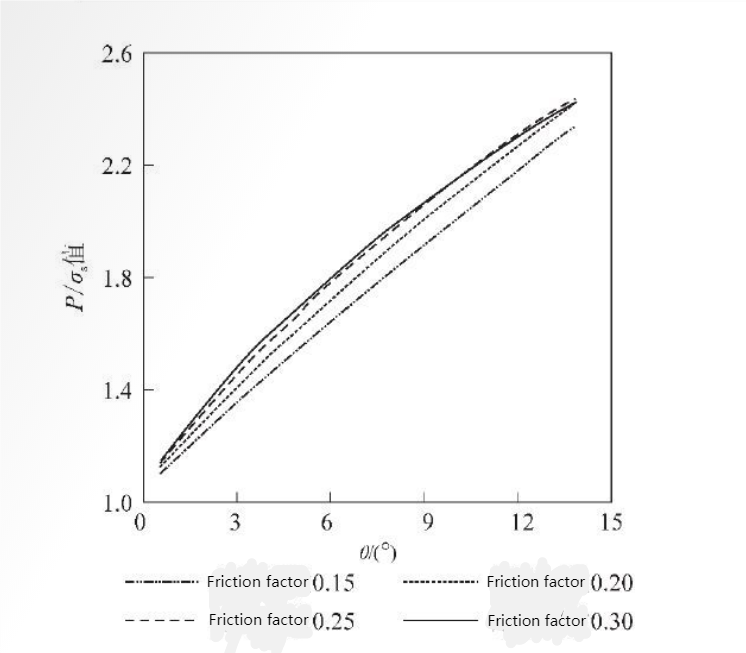
Fig.8 P/σs value curve from the bite point section (ϕ=13.61°) to the rolling out point section (ϕ=0)


 Eastern Steel Manufacturing Co.,Ltd not only improve product production and sales services, but also provide additional value-added services. As long as you need, we can complete your specific needs together.